Download
1 / 14
140 likes | 240 Vues
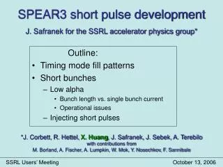
SPEAR3 short pulse development J. Safranek for the SSRL accelerator physics group*. Outline: Timing mode fill patterns Short bunches Low alpha Bunch length vs. single bunch current Operational issues Injecting short pulses.

E N D
SPEAR3 short pulse developmentJ. Safranek for the SSRL accelerator physics group* Outline: • Timing mode fill patterns • Short bunches • Low alpha • Bunch length vs. single bunch current • Operational issues • Injecting short pulses *J. Corbett, R. Hettel, X. Huang, J. Safranek, J. Sebek, A. Terebilowith contributions fromM. Borland, A. Fischer, A. Lumpkin, W. Mok, Y. Nosochkov, F. Sannibale SSRL Users’ Meeting October 13, 2006
Bunch structure in SPEAR standard fill: … “camshaft” fill: … Camshaft bunch lifetime (6, 2) hours for (5, 20) mA camshaft bunch 5 x 20 mA fill: … Lifetime ~2 hours without increasing vertical beam size.
Short Bunch Implementation Schemes (nominal SPEAR bunch length = 17 psec rms) • Equilibrium schemes • Low momentum compaction (low-) lattice • - < 1 – 6 ps rms, low current - emittance increase to 45 nm-rad • - many beam lines served, inexpensive • Harmonic cavity • - ~10 ps possible - many beam lines served, expensive • Superconducting crab cavities (Zholents) • - ~0.6 ps rms, - very few beam lines served, expensive • Non-equilibrium schemes • Normal conducting crab cavities • - ~1.5 psec rms, - 120 to 1000 Hz rep. rate • Injected beam mode • - inject and store short bunch for many turns, dump and re-inject • - < 1 ps @ 1.28 MHz burst, 0.1-1 nC/bunch, serving all beam lines • - expensive (short bunch injector, on-axis injection)
Equilibrium bunch length vs. ac • Bunch length (sz) depends on RF voltage (VRF) electron energy spread (sE), and momentum compaction (ac): • Increasing VRF is expensive; sE is ~fixed by synchrotron radiation. • Momentum compaction: • ac is the change in ring circumference, L, with electron energy • electrons oscillate about the bunch center in energy and time. • The amplitude of the oscillations in time (and thus sz) depends on ac.
Coherent Synchrotron Radiation (THz) • For wavelengths l > sz bunch radiates coherently, P ~ Ne-2. • CSR from tail of bunch acts on head of bunch, distorting bunch shape. • Bunch distortion extends frequency range of CSR, generating further bunch distortion. • This feedback drives beam unstable, lengthening the bunch at higher bunch currents. • CSR instability determines bunch length above instability threshold. • only at low bunch current • CSR photon beamlines developed at BESSY-II. Simulations by F. Sannibale, LBNL
SPEAR3 measured bunch length vs. current nominal bunch length: 17 psec CSR microbunch instability threshold defines bunch length for large bunch current. Theory: Stupakov and Heifets, PRST-AB, May, 2002. • Small-a, minimum bunch length: Itotal [mA]100 17 0.28 0.028 Ibunch [mA] 357 61 1 0.1 smin[psec] 6.9 3.8 1.0 0.45 Itotal = 280* Ibunch
Feikes et al., EPAC2004 Low alpha at BESSY-II • CSR m-bunch instability threshold defines bunch length vs. current*: • For small a, minimum bunch length: • Similar results in Japan, NewSUBARU Theory: Stupakov and Heifets, PRST-AB, May, 2002. BESSY-II bunch lengths: Ibunch [mA] 357 61 1 0.1 smin[psec] 8.4 4.3 1 0.4 Y. Shoji et al.
Low-a operational considerations • Optics modification increases beam size • Longitudinally stable • For small ac, dynamics depends on higher-order terms • SPEAR3 naturally has ac2, ac3 for longitudinal stability. • (Not so at ALS.) • Can reduce ac by 1000 or more • No multi-bunch instabilities. Stability requirement: • Reasonable lifetime, 13 hours at 100 mA (x4 less than standard optics) • Injection more challenging, lower injection rates • Work ongoing to reduce ~1 psec rms oscillations driven by RF.
Orbit stability in low a Feedback doesn’t fix high frequencies (yet) Large x-orbit variations ~h (no feedback) Feedback fixes slow x motion 6.5 hours 0.7 mm xy
BPM performance at low current • Beam position monitors noisy on west side of ring (BL1,2,11) at low current. • RF (476 MHz) getting into BPM electronics. • On east side, BPM noise ~1mm at 0.3 mA. BPM performance, west side:
Injected Beam Mode CSR Energy loss/turn vs. bunch length 0.1 nC, 0.1 % initial p/p • Inject short pulses into SPEAR (from SLAC linac?) & circulate until bunch length degrades. • Desired: 1 psec FWHM, 1 nC, 50-100 turns. • Simulations show: • 1 psec FWHM, 0.8 nC, 15 turns • Requires ~6 MV RF for CSR losses … $$. • Measurements at NewSUBARU • 1 GeV ring at Spring-8 • 6 psec FWHM, 0.02 nC lasted 50 turns 1 psec FWHM; 0.8 nC; Dp/p = (0.1% 1.0% ) Tracking by X. Huang
Conclusions • Low alpha lattice is ~ready to go • 7 psec rms at 100 mA; 1 psec at 0.3 mA • Could be CSR source as well • Injected beam study ongoing. • Plan to investigate crab cavity further. • We’re open to suggestions.