Download
1 / 37
370 likes | 596 Vues
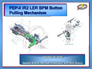
PEP-II IR2 LER BPM Button Pulling Mechanism . October 25, 2006 Nadine Kurita, Michael Kosovsky, and Nick Reeck. Motivation. Low Energy Ring (LER) Beam Position Monitor (BPM) feedthroughs are experiencing button heating. Button. Motivation, Cont’d.

E N D
PEP-II IR2 LER BPM Button Pulling Mechanism October 25, 2006 Nadine Kurita, Michael Kosovsky, and Nick Reeck
Motivation • Low Energy Ring (LER) Beam Position Monitor (BPM) feedthroughs are experiencing button heating Button
Motivation, Cont’d • BPM feedthroughs cannot easily be replaced, as they are welded into the chambers • To replace, every chamber would need to be removed. Then each feedthrough would need to be: • Ground off the chamber • Replaced with a new BPM feedthrough • Electron beam welded into chamber • Cost and time prohibitive; need an alternate solution Weld
Purpose • The purpose of the button puller is to remove the BPM buttons from the existing vacuum chambers without removing the chambers (in situ). • Remaining 2.4 mm pin functions as new “button” CHAMBER BPM
Access • Nearly every BPM chamber has a bellows on at least one end of the chamber. • The bellows can be removed to give chamber access. BPM Location Bellows
Access • There is approximately 4” (101.6 mm) between the chambers available for the mechanism to be inserted into the chamber when the bellows is removed. ~4” Gap
Assembly Sequence Borescope Collet Handles Locking Screw Anchor Shafts
How It Works The collet is carefully positioned below the button • The borescope is used to guide the collet into position Button Collet
How It Works, Cont’d With the collet in position, the cam shaft is activated by rotating the cam handle. Cam Handle
How It Works, Cont’d • The cam shaft transforms the rotational motion into translational motion. • The cam shaft consists of two cams that are lagging 90 deg to each other. The inner cam operates the Collet; the outer cam operates the Outer Plunger, PF-343-650-14. Collet Cam Shaft Outer Plunger Outer Plunger Cam Collet Cam
Lab Testing • Prior to use in the tunnel, we verified operation in the lab. • Worked exactly as intended • Did not break a single pin in 10+ button pulls Borescope Image Inserting puller into the chamber
BPM 3” to 72” In the Tunnel • BPM distance from the end of the chamber varies from 3” to 72”. • Alignment with button tricky, often time-consuming CHAMBER
Pin Breakage • On average, one pin in every 4 feedthroughs is broken. Fractures may occur due to: • Pre-existing cracks in the pin (brittle fracture) • Slight misalignment of button puller • “Cold welding” of the button to the pin • In every case, fracture occurs at diameter change in pin (the logical fracture site) Pin Fracture Site
LER Arc 1 Arc 3 Progress • GREEN = Completed location • RED = Yet to be pulled • As of Monday, October 23: • 97 out of 117 buttons pulled (83%) • 26 out of 97 buttons pulled broke the pin (27%) 2032 3132 2164 2082 2142 2112 3184 3149 3102 3072 3041 2056 3052 1162 2182 3172 IP 2052 3182 3112 2122 3062 3042 2172 2152 3082 2185 2092 2062 3162 3142 2022
PEP-II LER Arc BPM Replacement PEP-II BPM Retrofit Update October 25, 2006 Nick Reeck & Nadine Kurita
Existing LER Arc BPM Feedthrough 15mm Button Housing Ceramic Disc (or “Glass”) Pin SMA Jack Cross section of existing BPM (SA-342-601-26) with parts labeled
Option 1: Pull Button, Leave Pin • Pull off 15mm button, leave the pin as a 1.4mm “button” • Pros: • Simple • Cheap • Cons: • May lose some resolution, especially in single bunch, single pass
Option 2: Press Fit • Pull off 15mm button, press on a 7mm button • Pros: • “On Site” modification (slight radioactivity a concern) • Good electrical contact • More robust that old buttons • Cons: • Button press largely “trial and error”, have to measure buttons and pins to .0001” • Lots of SLAC labor
New BPM Feedthrough • Remove old BPM feedthrough, install new BPM feedthrough • Pros: • Better thermal conductivity (Boron Nitride disc) • Very robust • Excellent electrical contact • Less SLAC labor • Cons: • More expensive
New BPM Design Borosilicate Glass One-Piece Button and Pin Laser Welds Boron Nitride Disc
Electropolishing the Moly • Purpose: Smooth surface cracks to reduce stress concentration points • We wish to reduce or eliminate the failure mode seen in IR-2 BPM feedthroughs • As can be seen in these photos, electropolishing is effective 3 Minutes 1 Minute Before
Electropolish Fixture • Made a fixture to hold the parts during electropolish (~700 parts electropolished to date). • Prevents pins from being electropolished; rough surface likely helps glass adhesion during firing Electropolish Fixture Molybdenum Button / Pins
Bakeout • First 44 BPM feedthroughs were placed in a can for bakeout • Vac shop could not get the can to pump down • XPS Results – marginally clean parts, but high vapor pressure contaminants • Magnesium, sodium, calcium, sillicate, carbon • Add up to 36 atomic percent of surface composition • BPM feedthroughs were cleaned at SLAC (degreased), put back in can for bakeout on Thursday, October 19 • Still somewhat dirty, having trouble pumping down • As of Monday, October 23 we do not have RGA data
Installation Schedule (estimate) Arc 1 11/3 – 11/10 Arc 11 12/7 – 12/14 IP Arc 9 12/1 – 12/7 Arc 3 11/10 – 11/17 Arc 7 11/24 – 12/1 Arc 5 11/17 – 11/24 (Assumes 2 crews, 2 weeks to complete each arc)
Phases of Operation • Once the collet is in position, there are four phases during one shaft handle rotation. • One complete shaft rotation is necessary to pull the button
Phase 1 • 0-90 degrees: The Collet is being inserted into the .04” radial gap and engaged with the BPM button. The Outer Plunger is dwelling. Outer Plunger Collet
Phase 2 • 90-180 degrees: The Collet is dwelling in the inserted position. The Outer Plunger is moving upward to force the collet fingers tightly around the button.
Phase 3 • 180-225 degrees: The Collet, with the engaged BPM Button, travels a half stroke (4mm) downward. Hence, the BPM button is being removed (pulled from the BPM pin). The Outer Plunger is dwelling in the upward position, preventing the Collet from disengaging from the BPM button.
Phase 3, cont’d • 225-270 degrees: The Collet, with the engaged BPM Button, travels the rest of the stroke (4mm) toward chamber center plane. The Outer Plunger is dwelling in the inserted position.
Phase 4 • So, one 360 degree rotation of the shaft handle removes one BPM button. • 270-360 degrees: The Collet, with the removed BPM Button, is dwelling in the lower position. The Outer Plunger is moving towards the chamber center plane to its lower position.
Disassembly • The mechanism is then disassembled. The BPM button and the mechanism are removed from the chamber.
Top Left Top Right (Looking Into Chamber) Bottom Right Bottom Left Mechanical Design (cont.) • To remove the next BPM Button the cycle is repeated. • The mechanism is rotated 180 degrees about the vertical axis to remove the right versus the left BPM buttons • The mechanism is rotated 180 degrees about the horizontal axis to remove the top versus the bottom BPM buttons.
Installation Schedule • Delivered • October 11 – 45 units • October 20 – 150 units (195 total) • To Be Delivered • October 27 – 150 units (345 total) • November 8 – 150 units (495 total) • November 15 – 150 units (645 total) • November 22 – 150 units (795 total) • November 29 – 105 units (900 total)