Download
1 / 66
660 likes | 1.31k Vues
Diagnostic Imaging of Bones and Joints. Introduction to Orthopedic Radiology. Why PT’s Need to Know About Medical Imaging. To correctly interpret radiologists written report To speak the same language as physicians To enhance awareness of patients condition

E N D
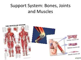
Diagnostic Imaging of Bones and Joints Introduction to Orthopedic Radiology
Why PT’s Need to Know About Medical Imaging • To correctly interpret radiologists written report • To speak the same language as physicians • To enhance awareness of patients condition • Radiologist reports are often written for the MD’s and may not take into account information the PT needs to treat the patient and to adequately formulate a prognosis
Important Facts About Xrays • Plain film radiography remains as the 1rst order diagnostic imaging modality • Xrays are a form of electromagnetic radiation similar to visible light but of shorter wavelength • Xray tube generates xrays and beams them toward the patient. Some of the energy is absorbed; rest passes through patient and hits the film plate. • Shades of gray on film are a representation of the different densities of the anatomic tissues through which the xrays have passed.
Tissues with greater density will absorb more of the xray so less of the beam reaches the film plate. The resultant image is therefore lighter. Tissues with less density will allow more xray to reach the film so it will be darker. This is called radiodensity and is determined by: *composition of the structure *thickness of the structure
BODY COMPOSITION AIR: Black Examples- trachea, lungs, stomach, digestive tract FAT: Gray black Examples- subcutaneously along muscle sheaths; around viscera
Continued WATER: Gray Examples: Muscles, nerves, tendons, ligaments, vessels (All of these structures have the same density and therefore are hard to distinguish on plain xrays.)
Continued BONE: Gray/White CONTRAST MEDIUM: White Outline HEAVY METALS: White Solid
PERCEIVING 3 DIMENSIONS The center of the xray beam is always perpendicular to the film plate. The position of the body will determine the outline of the image. SEE FIGURES 5 -6
ROUTINE RADIOLOGIC EVALUATION Consists of the angles of projection that best demonstrate the anatomy while utilizing the least amount of exposures. Common Views: • Anteroposterior (AP) • Lateral (R and L) • Oblique (R and L) (See Figure 7) Patient positioning for each projection is standardized throughout the USA
VIEWING RADIOGRAPHS • In AP and Lateral views, the film is always positioned on the view box with the patient positioned as if facing the viewer in anatomical position. • Hands and feet are placed with fingers or toes pointing up • Lateral views are placed on the box in the direction that the beam traveled. • Magnetic markers are used for R and L. Use this as the reference to place the patient facing the viewer in anatomical position (Fig 8)
FACTORS INFLUENCING QUALITY OF XRAYS • Detail: Geometric sharpness. Can be affected by movement • Distortion: Difference between the actual imagery and the recorded image. Geometric distortion occurs as the beam progresses away from the perpendicular. Fig. 9
Continued • Contrast: Difference between adjacent images. It is controlled by adjusting the energy of the beam.
ANATOMY OF BONE Compact Bone: forms outer shell or cortex of bone; dense Cancellous Bone: forms the inner aspect of bone except for the marrow cavity; spongy
FIGURE 10 Periosteum: Covers the cortex; fibrous layer which contains blood vessels, nerves and lymphatics. Endosteum: Membrane lining the inner aspect of the cortes and medullary (marrow) cavity Diaphysis: Shaft Metaphysis: Flared part at either end of shaft Epiphysis: Either end of the bone
PROCESSES OF BONE GROWTH • Ossification: Process of replacing cartilagenous model with bone • Endochondral Ossification: How bones grow in length • Intramembraneous Ossification: How bones grow in width • Physis: The growth plate evidenced by the “open space” Fig 11 and 12
10 yo male normal AP and mortise view
REMODELING OF BONE WOLFF’S LAW Bone will be deposited in sites subjected to mechanical stress with trabeculae aligning in ways that best absorb stress. Bone will resorb from sites deprived of stress. Clinical Relevance: As soon as it is safe, weight bearing should be allowed through the bones
ABC’S OF VIEWING FILMS A: ALIGNMENT 1. Assess the size of the bones: gigantism, dwarfism, etc 2. Assess the number of bones 3. Assess each bone for normal shape and contour; irregularities can be from trauma, congenital, developmental or pathological 4. Assess joint position: trauma, inflammatory or degenerative disease (Fig 13)
B. BONE DENSITY 1. Assess general bone density *contrast between soft tissues and bone *contrast between cortical margin and the cancellous bone and medullary cavity *loss of contrast means loss of bone density ie: osteoporosis *labeled as osteopenia, demineralization or rarefaction
Originally coined for the changes of senile osteoporosis, biconcave deformities of the vertebral bodies ("fish vertebrae") are characteristic of disorders in which there is diffuse weakening of the bone. The name is derived from the actual appearance of a fish vertebrae which normally has depressions in the superior and inferior surfaces of each vertebral body. This sign is typically used for osteopenia.
2. Assess local bone density: looking for sclerosis; sign of repair in the bone. Excessive sclerosis is indicative of DJD. (Fig 15) Bone Lesions: Osteolytic- bone destroying so appear radiolucent as in RA or Gout (Fig 16) Osteoblastic- bone forming; osteoblastomas, osteoid osteomas 3. Assess texture abnormalities: looking at trabeculae appearance
C. CARTILAGE SPACES 1. Assess joint space width 2. Assess subchondral bone 3. Assess the epiphysis and growth plates
s: SOFT TISSUES 1. Assess the gross size of the musculature (Fig 17) 2. Assess outline of joint capsules: normally indistinct; become obvious during episodes of increased joint volume from infection, hemorrhage or inflammation 3. Assess the periosteum: normally indistinct; (Fig 18)