Developing a Real-time System Architecture
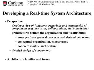
Developing a Real-time System Architecture. Perspective develop a view of functions, behaviour and (tentatively) of components (e.g. use cases, collaborations, static modeling) architecture: defines the organization and its attributes emerges from general concerns and desired behaviour

Developing a Real-time System Architecture
E N D
Presentation Transcript
Developing a Real-time System Architecture Perspective develop a view of functions, behaviour and (tentatively) of components (e.g. use cases, collaborations, static modeling) architecture: defines the organization and its attributes emerges from general concerns and desired behaviour conceptual organization, concurrency concrete module architecture detailed design of components Architecture families and issues
What is architecture? • organization of components and interactions • what components • more important for larger more complex systems • especially prominent for systems with concurrent processes. • distributed • parallel • real-time (to meet deadlines) • architecture establishes the requirements for detailed design
Recognize typical architectures • Hierarchical: control at the top • client server: info retrieval; client pulls information up • master-slave: processing; master pushes commands and data down • Hierarchical: control distributed • higher levels have a wider perspective but changes enter at the periphery • Pipeline: data flows through • control at a higher level, over all • control at one end • at beginning, control flows along same path as data, or separate, and pushes data through • at end, control goes in reverse direction and pulls data through • Shared memory (memory, database, tuple space, DSM, etc) • Messaging (point to point, broadcast, publish and subscribe)
Process of deriving and evaluating it... • The subject of Applied Software Architecture, by Hofmeister, Nord and Soni (HNS) • Global concerns • Factors: of the product, technology to be used, and the developer organization. • for each factor: identify, describe, volatility, impact • Issues arising from the factors • solutions or strategies for dealing with issues • Conceptual architecture • conceptual components/interactions are described by their requirements or their attributes, rather than as designs ..... (e.g. half-call controller) • focus is on high-level control and functional interactions rather than actual internals.......components all potentially concurrent... • very like the RoseRT view!! • we will reason from UCMs • we will consider necessary concurrency issues more seriously here, using UCMs...
Process of... (2) • Module architecture view in next step.... more concrete • possibly re-arranged, from evaluation of resource requirements • intended real components, with real interactions • at the object level, these are the elements of Gomaa’s architecture, • his four types of object (interface, entity, control and application logic) • high-level control usually becomes meshed into execution of functions • again, we will consider necessary concurrency • UCM is now only a reference for tracing back to the big picture • .....Gomaa seems to leap directly to this step • Execution architecture view expresses configuration questions • processes, threads, processors, OS, midware • concurrency is settled here, by HNS • location, migration of functions
Role of UCMs • initially to establish what is being talked about • what operations • what components • allows architecture to be modified and manipulated, to address issues • semantics of the UCM model • reasoning about UCMs • Navigator tool
Image processor example (HNS) • platform... • probe with camera and other sensors, and motion control; • acquisition by imaging computer • control and viewing at control station; • remote viewing/processing stations • operations: • image or image-sequence acquisition, • built-in and user-defined acquisition procedures • acquisition and display rate, speed/quality tradeoff • image processing and storage, • display at control station • export for remote viewing or processing
Requirements • examples.... • data rate for acquisition and display • upgradeable (platform, OS, camera, sensors, algorithms) • recovery from failures during acquisition
Image processor UCMs (1) Probe Acquisition User Control Interface Postprocessing acquisition controls display controls acquire probe data format postprocess view Database store export controls send Network
Creating an Architecture: HNS approach based on a “global analysis” • Identify factors of several kinds.... these are relevant aspects. • they suggest factors coming from the product, technology, organization • factors have an aspect of stability, and of impact • Identify issues related to the factors • goals, potential problems • an issue can arise or involve several factors • Create strategies for dealing with the issues • Use the strategies in creating the architecture • this is a creative process using ingenuity, with no right answers
Global analysis: product factors • Functional features • acquisition procedures: may change every 2 years, affects performance, image processing, and the UI • image processing: library; algorithms change, affects image processing and UI • image types: new types may be added, affects storage, acq. and image-p., and export • UI • interactive control of acquisition: changes approx 3 years, affects UI, acq. and storage • user defined parameters: stable, affects acquisition and storage • Performance • data rate from probe: changing with probe hardware, affects acquisition performance • performance requirements: not quite stable • Dependability... • Failure handling (detect/report/recover)... • Servicing... • Cost: budget amounts: inflexible.... affects the components for image acquisition • Example issue: easy addition and removal of features • idea: separation of components by concerns
Global analysis...technology factors • processor type: frequent changes, expected to be transparent • memory: 64 MB chosen to keep cost down... could be increased... would allow more complex image processing. • probe hardware (to detect and capture signals) and interface: expect upgrades every 3 years... affects acquisition and image processing • OS: real-time kernel on standard processor... features change in 2 years, OS change in 4 years • OS: POSIX compliant... stable.... affects all software • Image data format is standardized... likely to change every 3 years... large impact on image processing and post-processing. • Image-processing algorithms... stable... minor impact • Example issue: Changes in hardware are expected...processor, probe, interface • idea... encapsulate the changes by a software interface. • another: changes in software technology: OS, and software components • idea... encapsulate with in-house interfaces
Global analysis...organizational factors • Management: build-vs-buy: ready to buy... helps to meet schedule • schedule vs functionality: schedule has priority...ready to compromise on features: impact on first release date • Staff skills: OOA and design: some designers have skills... training is possible... moderate impact on good design • multithreading and multiprocessing: limited skills... threading is too complex for training in the time... moderate to large impact on performance • Schedule: time to market 2 years... no flexibility... large impact on choices • Features: features are prioritized and somewhat flexible... moderate impact on schedule • Budget: head count is X... impact on schedule • Issue: Aggressive Schedule needed
Global analysis...issues lead to strategies Strategies arise from analysing issues... they can be related to several factors... they affect the architecture. • example arising from organizational factors: Aggressive Schedule Issue • three strategies suggested: • re-use existing in-house components • buy rather than build • make it easy to add/remove features (and reduce initial functionality) • example from technology factors: Changes in Hardware (probe, processor) • strategy suggested: • encapsulate the hardware with software that offers a general interface • another: Changes in Software Technology... strategy: use standards • example from product factors: Easy Addition/Removal of Features • three strategies suggested: • separate components by concerns (processing, communications, control, data, UI) • encapsulate features in separate components • decouple the UI model from the rest • another: Throughput • strategy: • use concurrent processes for independent threads of control • another: Acquisition performance • strategy: • separate time-critical components from others • use shared memory • another: Recovery from errors... strategy: • introduce a recovery feature with persistent data
Develop Conceptual Architecture • Use cases and UCMs • Global analysis leads to some strategies which are architectural, for instance: • easy addition/removal, when applied to the acquisition and processing steps, suggests the use of specialized components and three strategies: • a flexible pipeline model for both kind of processing (components can be snapped in) • interfaces become a concern... • components for specific features • encapsulate domain-specific data in generic structures • acquisition performance suggested separating the time-critical components in the image-capture and processing chain, from others • Consider the previous UCM but change the components to separate the time-critical imaging operations (data handling during actual acquisition) from control, storage and export • Pipeline structure and components for processing are a more detailed concern for later.....
Conceptual Architecture... redivide the UCM Probe Acquisition User Control Interface Postprocessing Acquisition acquisition controls display controls Imaging acquire probe data format postprocess view Database store Exporting export controls send Network
Conceptual Architecture in UCM Acquisition Acquire acquisition controls acquisition management probe control display controls Monitor Imaging collect process probe data postprocess format view Export Database store Exporting export controls retrieve send Network
Architecture notation in HNS Component • Components with ports • (stereotype ccomponent of UML Active class) • may have nested components (UML Composition) • Ports • (stereotype cport of UML Class) • have bindings to roles, (cbinding, st of UML Association) • have connections to ports for nested components (cconection, st. of UML Association) • bindings have protocols defined as in ROOM (message lists in each direction) • First-class connector with roles • (stereotype cconnector of UML Active Class) • connect components with the same encapsulation • may contain components and connectors, to describe complex connectors like an ORB, for instance • Roles (eg, sender, receiver) • (stereotype crole of UML Class) • binding to ports, and to roles of nested connectors nested component connection Port binding (and protocol) Connector Role Component
Explanation of Conceptual Components • Probe Control: encapsulates the probe control interface for probe motion and acquisition, and configures the Data Collection component • Acquisition Management: configures the image processing and the probe • Acquire: provides the UI for acquisition. • Data Collection: encapsulates the probe data interface and transmits raw data • Image Processing: converts the raw data to image frames • may include a pipeline of functions for data formatting • Post Processing: applies image enhancement algorithms • may include a pipeline of functions • Monitor: encapsulates the user display and its controls • Image Collection: captures and stores images for later export. Can also provide the stable storage needed for error recovery. • Export: provides the UI for exporting images to other workstations • Comm: handles network communications with other workstations.
UCM over HNS Conceptual Architecture • Stubs for ImageProcessing and PostProcessing • configured by control
Decomposition of ImageProcessing component acqControl packetize process
Conceptual Components of ImageProcessing • Packetizer converts raw data to packets • PacketPipe conveys packets to the processing part • ImagePipeline is some number from zero up, of subsystems in parallel • cardinality shown by * (UML... implicit cardinality of 1)) • this could in principle allow parallel enhancement processing on segments of the picture, if a multiprocessor were installed • ImagePipeline is provided to hold the pipeline planned for the image preprocessing... this might include noise filtering and compensation for probe response.
Conceptual Components of ImagePipeline • PipelineMgr is created for a particular acquisition, configured for the acquisition procedure. • it configures the entire pipeline of functions, and then manages the flow of frames through the pipeline. • it initializes stages, and the sequence of stages, depending on the acquisition procedure • it requests the start of processing • Client/server is a conceptual connector which initializes the Framer and each Imager stage • Event is a conceptual connector which initiates processing of an image. • Framer begins at an event... it pulls packets from the Packetizer, and creates meaningful image frames from the packets, according to a standard • ImagePipe is a conceptual connector which conveys frames, using the standard • Imager is one of a sequence of pipeline stages which carries out some image-processing algorithm on the image frame
Recovery Issue • data that has been acquired should not be lost in a failure (crash, or power failure), but it should be possible to continue on from that point • raw data or processed? since processing is done as data is acquired, we will say, processed. • we have it stored now. • suggested: a recovery subsystem, with dedicated components for cleanup and crash recovery • UI elements to allow the operator to make choices about the restart • discovery of the point at which recovery is to start: this may require additional data to be saved • configuration and acquisition procedure definition • state of all components periodically?? • suggested: a separate recovery mode for each conceptual component. • recovery control path • access to data for re-initialization
Diagnostics Issue • separate from recovery, is the logging of information to help understand problems. • logging • access to logs • suggested: diagnostic reporting from all components • uniform policy • one embedded component for detecting and logging, one for access (consider: should access really be by component, or for the whole system??) • suggested: use common tools to define and deliver error messages • (issue: reduce effort) • suggested: use standard logging services
Resource budgeting • memory budgets for components in the image flow path • time budgets for executing functions on the image flow path • reaction time budgets for reacting to command events? • e.g., a data rate of 2 MB/sec for probe data
Evaluation • evaluate the conceptual architecture, particularly against the global analysis issues, and revise if necessary. • ... architecture evaluation to be revisited
Module View Architecture • what it is... how different • a repartitioning to generate the actual class architecture for large modules. So: • a module will have an implementation • a module may be one or more conceptual elements • may differ from conceptual partitioning, based on evaluation • Layers, subsystems and modules • modules accept calls or messages, do all their own interpretation and mediation • Layers.... suggested by level of abstraction (these look a bit like our initial UCM-based components, however!) • GUI • Applications: management, postprocessing, storage and export operations • ImageProcessing: preprocessing stuff • probe services: probe control, data collection • system services • ?? logging.... recovery??
Layers • Commonly associated with level of abstraction • high levels of abstraction have more coverage: • scope across a variety of system functions and components • across the timeline of an operation • across larger units of data Control operationsLayerData scope HI.. setup acq. procedure UI whole sequence sequence the pipe steps Mgt/App individual images trigger build frame ImageProc framing and image building position probe, set Probe bitstream from probe controls LOW probe operations System Services Hardware
Layers Fig 5.4 • GUI • Applications, includes management and the non-time-critical parts of acquisition • (mixes whole-process and single-image-step handling... keep an eye on this?) • ImageProcessing includes the time critical parts, which must keep up with the probe data rate. • mixes bitstream, frame and first image stage • ProbeService includes the probe interfaces for control and data • SystemServices includes the communications for export. • notice the mixed motivations... layers can be anything...
Layers • tend to have inter-layer “uses” relationships that go in one direction (e.g. “down”) • within a layer there may be sublayers... or anything goes. Processing moves up in abstraction here, and control moves down: control operations data movement Data scope whole sequence image scope framing bitstream from probe time setup start collecting stored result
Elements of module architecture • module, interface, package........ visibility of interfaces <<subsystem or layer>> <<module>> ModuleA requires interface InterfaceB provides interface <<module>> ModuleB
alternative description, for interface operations <<module>> ModuleA dependency <<module>> ModuleA <<interface>> InterfaceB requires interface no attributes for an interface read() update() interfaceB realization realization <<module>> ModuleB <<module>> ModuleB
Where do we get modules from? • conceptual components • functions • ports and connectors, even roles... • it may be useful to focus first on ports and connectors and build up the architecture from the edge in, as described in HNS: • in ImageProcessing (fig 4.7), the Packetizer and the PacketPipe can be merged to get a buffer manager “MPacketizer” that builds packets and manages a packet buffer • this is accessed by the next component to fetch the packet • next, the packetIn port becomes a MPacketMgr, for Framer to access packets and build an image. • Framer is a module, and writes images to a module MImageMgr, which manages an Image buffer • this MImageMgr handles image communications between stages (?)
Styles of module architecture: pipeline • push, • pull, • mixed IF1 IF2 IF3 Stage1 Stage2 Stage3 IF3 IF1 IF2 Stage1 Stage2 Stage3 IF3 IF1/2 IF2 IF1 Stage2 Stage3 Stage1 doesn’t say anything about passing the data... could be by calls...
Pipeline with storage between stages IF1 • separate buffers • global buffers Stage1 Stage2 Stage3 IF1/2 IF2/3 Buffer1/2 Buffer2/3 IF1 Stage1 Stage2 Stage3 IBuffer GlobalBuffer
Styles of module architecture: hierarchy ITask Client-server Master-slave Inverted Master-slave ITask Client1 Client2 Master Slave1 Slave2 ISlave1 ISlave1 IServer Server Slave1 Slave2 IServer ICmd Server IServer2 IServer Master Server2 Server
Hierarchy with shared storage Client-server,,,, Client1 Client2 IServer Server IStore SharedStore
Peer - to- Peer architectures Direct interaction Publish and Subscribe (e.g. by tuple space) Peer1 Peer2 Peer3 Peer1 Peer2 Peer3 Shared memory Peer1 Peer2 Peer3 IStore ITS Store TupleSpace
example as shared-memory module architecture :CustomerInterface :OperatorInterface :CardReaderInterface IServer cardReaderBuffer ATMControl MessageQ :ATMController promptMessageQueue bankServerProxy
Subscription/notification.. Gomaa fig 13.13 Inotify Client Isubscribe/query :Server Coordinator :Subscription Server IServer :Event Monitor :Event Distributor IEvent Iarchive Archive
Principles for concurrency in architecture • concurrency is provided by separate tasks and threads • task is the same as process, a program unit dispatched by the OS • provide a concurrent task for: 1. managing an interface 2. a separate thread of control (cohesion) (separate responses) 3. parallel operations to provide capacity or speed 4. urgent operations, so they can be scheduled with priority 5. put together modules that communicate heavily (IPC is expensive) 6. components that might be replaced (because of the generality of the message-passing interface between processes) 7. a server for shared data that needs management (e.g. mutual exclusion) 8. conceptual components, if they line up with modules (HNS...)
Concurrency and Tasks... HNS Image-processor Summary of the modules in the imaging data stream initiates control one controller per pipeline responsiblility for managing access to image buffers makes images from packets packet buffer manager pipeline stage (many) mediates access by a stage to image data
Derivation of pipeline tasks... from HNS client = thread of control AcqControl is bound to it by messages process per thread of control (framer = one pipeline stage) conceptual /module agreement task per pipeline (different code) process per thread of control (one pipeline stage)
Pipeline creation... one pipeline instance • one client for many pipelines • one pipeline has its own image buffer, manager, framer (!!) and one or more imager processes
All imaging tasks IPC is message-passing supported by kernel primitives, all on one bus and even in one processor one AcqControl per pipeline packetizer task mimic tasks and memory for Pipeline control image data access pipe stage frame from packet * for “many”