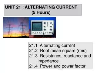
UNIT 21 : ALTERNATING CURRENT (5 Hours)
UNIT 21 : ALTERNATING CURRENT (5 Hours). 21.1 Alternating current 21.2 Root mean square ( rms ) 21.3 Resistance, reactance and impedance 21.4 Power and power factor. SUBTOPIC :. 21.1 Alternating Current (1 hour). LEARNING OUTCOMES :.

UNIT 21 : ALTERNATING CURRENT (5 Hours)
E N D
Presentation Transcript
UNIT 21 : ALTERNATING CURRENT (5 Hours) 21.1 Alternating current 21.2 Root mean square (rms) 21.3 Resistance, reactance and impedance 21.4 Power and power factor
SUBTOPIC : 21.1 Alternating Current (1 hour) LEARNING OUTCOMES : At the end of this lesson, students should be able to : • Define alternating current (AC). • Sketch and interpret sinusoidal AC waveform. • Write and use sinusoidal voltage and current • equations. 2
21.1 Alternating current • An alternating current (ac) is the electrical current which varies periodically with time in direction and magnitude. • An ac circuit and ac generator, provide an alternating current. • The usual circuit-diagram symbol for an ac • source is .
The output of an ac generator is sinusoidal and varies with time. • Current where: I : instantaneous current @ current at time t (in Ampere)
voltage where: V : instantaneous voltage @ voltage at time t (in Volt)
Vo Io T/2 T • The output of an ac generator is sinusoidal • and varies with time. Equation for the current ( I ) : Equation for the voltage ( V ) :
Terminology in a.c. • Frequency ( f) • Definition: Number of complete cycle in one second. • Unit: Hertz (Hz) or s-1 • Period ( T ) • Definition: Time taken for one complete cycle. • Unit: second (s) • Equation : • Peak (maximum) current ( Io) • Definition: Magnitude of the maximum current. • Peak (maximum) voltage ( Vo) • Definition: Magnitude of the maximum voltage. • Angular frequency ( ) • Equation: • Unit: radian per second (rads-1)
SUBTOPIC : 21.2 Root Mean Square (rms) (1 hour) LEARNING OUTCOMES : At the end of this lesson, students should be able to : • Define root mean square (rms), current and voltage for AC source. • Use , 8
21.2 Root mean square (rms) Root mean square current (Irms) is defined as the effective value of a.c. which produces the same power (mean/average power) as the steady d.c. when the current passes through the same resistor. the average or mean value of current in a half-cycle flows of current in a certain direction
The r.m.s (root mean square) current means the • square root of the average value of the current. Root mean square voltage/p.d(Vrms )is defined as the value of the steady direct voltage which when applied across a resistor, produces the same power as the mean (average) power produced by the alternating voltage across the same resistor. V V=Vo sin ωt
only for a sinusoidal alternating current and voltage • The average power, • The peak power, • Most household electricity is 240 V AC which • means that Vrmsis 240 V.
Example 21.2.1 A sinusoidal, 60.0 Hz, ac voltage is read to be 120 V by an ordinary voltmeter. • What is the maximum value the voltage takes on • during a cycle? b) What is the equation for the voltage ? a) b)
Example 21.2.2 A voltage V= 60 sin 120πtis applied across a 20 Ω resistor. • What will an ac ammeter in series with the • resistor read ? b) Calculate the peak current and mean power.
and Example 21.2.3 The alternating potential difference shown above is connected across a resistor of 10 k. Calculate a. the r.m.s. current, b. the frequency, c. the mean power dissipated in the resistor.
Exercise 21.2 An ac current is given as I = 5 sin (200t) where the clockwise direction of the current is positive. Find • The peak current • The current when t = 1/100 s • The frequency and period of the oscillation. 5 A , 4.55 A, 31.88 Hz, 0.0314 s
SUBTOPIC : 21.3 Resistance, reactance and impedance (2 hours) LEARNING OUTCOMES : At the end of this lesson, students should be able to : • Sketch and use phasor diagram and sinusoidal waveform to show the phase relationship between current and voltage for a single component circuit consisting of • i) Pure resistor • ii) Pure capacitor • iii) Pure inductor 17
b) Define and use: • i) capacitive reactance, • ii) inductive reactance, • iii) impedance, , and • phase angle, • c) Use phasor diagram to analyse voltage, current, and impedance of series circuit of: • i) RC • ii) RL • iii) RLC 18
21.3 Resistance, reactance and impedance Phasor diagram • Phasor is defined as a vector that rotate • anticlockwise about its axis with constant angular • velocity. • A diagram containing phasor is called phasor • diagram. • It is used to represent a sinusoidal alternating • quantity such as current and voltage. • It also being used to determine the phase • difference between current and voltage in ac circuit.
Phasor diagram y y Ao N P O • The projection of OP on the vertical axis (Oy) is ON, • represents the instantaneous value. • Aois the peak valueof the quantity.
i) Pure Resistor in the AC Circuit VR Phasor diagram
i) Pure Resistor in the AC Circuit • The current flows in the resistor is • The voltage across the resistor VRat any instant is • The phase difference between V and Iis • In pure resistor, the voltage V is in phasewith the • current I and constant with time.(the current and the • voltage reach their maximum values at the same time).
i) Pure Resistor in the AC Circuit • The resistancein a pure resistor is • The instantaneous power, • The average power, A resistor in ac circuit dissipates energy in the form of heat
ii) Pure Capacitor in the AC Circuit • Pure capacitor means that no resistance and • self-inductance effect in the a.c. circuit. VR Phasor diagram
ii) Pure Capacitor in the AC Circuit • When an alternating voltage is applied across a • capacitor, the voltage reaches its maximum value • one quarter of a cycle after the current reaches its • maximum value,( ) • The voltage across the capacitor VCat any instant • is equal to the supply voltage V and is given by • The charge accumulates on the plates of the • capacitor is • The current flows in the ac circuit is
ii) Pure Capacitor in the AC Circuit and or • The phase difference between V and I is
ii) Pure Capacitor in the AC Circuit • In pure capacitor, • the voltageV lagsbehindthe currentIby/2 radiansor the current Ileadsthe voltage Vby /2 radians. • The capacitive reactance in a pure capacitor is • The capacitive reactance is defined as
ii) Pure Capacitor in the AC Circuit • The instantaneous power, • The average power, • For the first half of the cycle where the power is negative, the power is returned to the circuit. For the second half cycle where the power is positive, the capacitor is saving the power.
Example 21.3.1 ii) Pure Capacitor in the AC Circuit An 8.00 μF capacitor is connected to the terminals of an AC generator with an rms voltage of 150 V and a frequency of 60.0 Hz. Find the capacitive reactancermscurrent and the peak current in the circuit. Capacitive reactance, rms current, Peak current ?
iii) Pure Inductor in the AC Circuit • Pure inductor means that no resistance and capacitanceeffect in the a.c. circuit. VL Phasor diagram
iii) Pure Inductor in the AC Circuit • When a sinusoidal voltage is applied across a • inductor, the voltage reaches its maximum value one quarter of a cycle before the current reaches its maximum value,( ) • The current flows in the ac circuit is • When the current flows in the inductor, the back emf caused by the self induction is produced and given by
iii) Pure Inductor in the AC Circuit • At each instant the supply voltage Vmust be equal • to the back e.m.f B(voltage across the inductor) • but the back e.m.f always oppose the supply voltage V. • Hence, the magnitude of V and B , 0 or where
iii) Pure Inductor in the AC Circuit • The phase difference between V and Iis • In pure inductor,the voltageVleads the currentIby/2 radians or the current Ilagsbehindthe voltage V by /2 radians. • The inductive reactance in a pure inductor is
iii) Pure Inductor in the AC Circuit • The inductive reactance is defined as • Theinstantaneous power, • The average power, • For the first half of the cycle where the power ispositive, the inductor is saving the power. For the second half cycle where the power isnegative, the power is returned to the circuit.
Example 21.3.2 iii) Pure Inductor in the AC Circuit A coil having an inductance of 0.5 H is connected to a 120 V, 60 Hz power source. If the resistance of the coil is neglected, what is the effective current through the coil. Example 21.3.3 A 240 V supply with a frequency of 50 Hz causes a current of 3.0 A to flow through an pure inductor. Calculate the inductance of the inductor.
Phasor diagram i) RC in series circuit • In the circuit diagram : • VRand VC represent the instantaneous voltage • across the resistor and the capacitor. • In the phasor diagram : • VRand VC represent the peak voltage across the • resistor and the capacitor.
Phasor diagram i) RC in series circuit Note
Phasor diagram i) RC in series circuit • The total p.d (supply voltage),V across R and C is • equal to the vector sum of VR and VC as shown in • the phasor diagram. and
Phasor diagram i) RC in series circuit Impedance diagram • From the phasor diagrams, • The impedance in RC • circuit, Ileads V by Φ or
i) RC in series circuit Z R f 0 Graph of Z against f
Example 21.3.4 i) RC in series circuit An alternating current of angular frequency of 1.0 x 10⁴ rad s-1 flows through a 10 k resistor and a 0.10 F capacitor which are connected in series. Calculate the rms voltage across the capacitor if the rms voltage across the resistor is 20 V.
Phasor diagram ii) RL in series circuit • The voltage across the resistor VR and the capacitor • VL are
Phasor diagram ii) RL in series circuit • The total p.d (supply voltage),V across R and L is • equal to the vector sum of VR and VLas shown in • the phasor diagram. and
Phasor diagram ii) RL in series circuit Impedance diagram • From the phasor diagrams, • The impedance in RC • circuit, Vleads I by Φ or
ii) RL in series circuit Z R f 0 Graph of Z against f
Phasor diagram iii) RLC in series circuit
Phasor diagram iii) RLC in series circuit • The voltage across the inductor VL , resistor VR and • capacitor VC are
Phasor diagram iii) RLC in series circuit • The total p.d (supply voltage),V across L, R and C • is equal to the vector sum of VL ,VR and VC as • shown in the phasor diagram.