Download

1 / 34
340 likes | 449 Vues
Development of Hydrogen Safety Technologies in Japan. September 8-10, 2005 At PISA, Italy New Energy and Industrial Technology Development Organization (NEDO) Japan Tomohiko IKEYA. Development of Hydrogen Safety Technologies in Japan.

E N D
Development of Hydrogen Safety Technologies in Japan September 8-10, 2005 At PISA, Italy New Energy and Industrial Technology Development Organization (NEDO) Japan Tomohiko IKEYA
Development of Hydrogen Safety Technologies in Japan • IntroductionActivities to popularize PEFC Vehicles and Stationery system • Commercialization Scenario of PEFC by Government • Review of Safety Regulation for PEFC Vehicles, stationery systems and H2 infrastructures • Summary
Prime Minister KOIZUMI rode and drove FCEVs at Tokyo in 2002, December. “The ride is even smoother than ordinary automobiles. These are the ultimate environment-friendly cars, and considered from the perspective of ensuring the energy safety of our nation, this is an extremely important area of research and development.” The Government‘s policy encourages greater adoption of this technology. Fuel cells generate electricity achieve a much higher level of fuel efficiency and greater reduction of CO2 emissions. The Government intends to support R&D of this technology and experiments to demonstrate its practicality.
Performance Nominal capacity 1 kW Electric Efficiency More than 31% (HHV) Thermal Efficiency More than 40% (HHV) Hot water tank 200 L Fuel Methane The first commercial PEFC stationary systems installed into the new prime minister’s official residence in 2005, April. PEFC stationary system by Tokyo gas Panasonic Ebara-Ballard
Japan Hydrogen & Fuel Cell Demonstration(2002 to 2005) • Estimate more than 60 FCEVs and 12 hydrogen refueling stations around Tokyo, Yokohama and Aichi. • Evaluate the energy consumption and performance of FCEVs on road. • Compare the stations with several types of fuel reformer systems. Liquid Hydrogen storage LPG reform Tokyo Emperor palace Chiba Naphtha reform Methanol reform Yokohama Central Research center Gasoline reform
Carbon Dioxide Emissions in Japan Approximately 1.34 G tons of CO2 Emissions per year Energy conversion 30% Industrial Processes 4% Waste 2% Residential Sector 6% Transport sector 20% Commercial Sector 4% CO2 Emissions in Japan Reduction of CO2 emissions from transport and Energy conversion sectors will significantly benefit the environment and promote sustainability. And Co-generation system should be expected to enhance energy efficiency with supplement of both electricity and hot water. Industrial sector 30%
Low-emission Vehicles • Electric Vehicle • Short distance per charge, long charging hours required, utilizes a wide variety of fuels, no CO2 emissions,high cost of production • Compressed Natural Gas Vehicle • Relatively short distance per fill, infrastructure exists,uses fossil fuels,CO2 emissions • Hybrid Electric Vehicle • Mileage better than or equal to ICEV, existence of infrastructure (gas stations),consumption of fossil fuels, CO2emissions →more than 400,000 HEV in the world today • Fuel Cell Vehicle • Utilizes a wide variety of energy, no CO2 emissions,high efficiency expected, prohibitiveproduction costs
Why Develop Hydrogen & PEFCs Now? • Hydrogen for FCs, produced by a wide variety of energy resources, including renewable, nuclear and fossil energy, among others, reduces future dependence on fossil fuels. • With widespread use of fuel cells in industry and households, a reduction in CO2 emissions and energy consumption is expected. • FC vehicles reduce the impact of PM, NOx or SOxon the environment. • Potential for creating new industries and employment, and increasing industrial competitiveness. • Reduce energy loss in transmission and provide backup energy for emergencies.
Fuel Cell Commercialization and Diffusion Scenario 1: to 2005(Basic work and technology demonstration stage) - Drawing up FC R&D Strategy and its Implementation - Soft-infrastructure/Codes & Standards (Millennium project) - Demonstration 2: 2005 to 2010(Introduction stage) • - Acceleration of the Introduction • and Gradual Establishment of Fuel Supply System • - Leadership of Public Sectors as well as FC Industries in Promotion of FCV and Buses 3: After 2010(Diffusion stage) - Establishment of Fuel Supply System and Self-sustained Growth of the Market - Private Sector’s Promotion of the Introduction New Target Forecast of Fuel Cell Introduction 2010 20202030 FCV 50,000 vehicles 5,000,000 15,000,000 Stationary FC 2.2 million kW10 million 12.5million
NEDO R&D of FC/Hydrogen Projects Hydrogen Codes & Standards Millennium Project PEFC Toward 15M FCVs and 12.5GW of PEFC systems until 2030
Issues for Commercialization & popularization of PEFC • Enhance the performance of power, durability and efficiency • Reduce cost and simplify the system • Ensure hydrogen safety for FCV, Stationary system and H2 station R&D of PEFC and Hydrogen technologies R&D of Mass Production technologies Check & Review Safety Regulation and establish new codes & standards Review road map of 28 subjects in six laws checked in the code & regulations until March 2005.
Review road map of 28 subjects in six laws For FCVs to drive in cities • Adoption of type approval system including high pressure tanks is necessary for mass production of FCV • Permit a FCV to rush into a long tunnel or a tunnel under sea ? • Permit a FCV to park at underground or tower parking garages? • Ensure safety for high pressure hydrogen, and against hydrogen leak in vehicles and fire accidents Review regulation and establish new codes and standards Review road map of 28 subjects in six laws
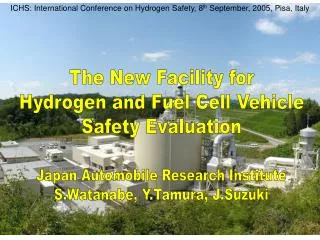
A New Facility for safety test of Fuel Cell Vehicles at JARI, to estimate safety against fire accidents for FCVs with high pressure tanks Inside the test circuit Hydrogen and Fuel Cell Vehicle Safety Evaluation Facility:Hy-SEF
Bonfire Test of high pressure tank at Hy-SEF 35MPa Hydrogen Vessel
Minimum Burst Pressure 78.75MPa 150 Ambient TemperaturePressure Cycling Burst Pressure 121.0MPa Hydrostatic Pressure Burst Test 100 Pressure:[MPa] Test Tank 50 Test Situation Before Burst 0 60 120 300 180 360 0 240 Time:[sec] Leak Water Filling Pressure 35.0MPa Pressure‐TimeDiagram After Burst Situation of LBB
Technical standard was prepared for compressed hydrogen vehicle tanks and tank attachments in 2004. Safety Evaluation of High Pressure Storage Tank High Pressure Storage Tank - Test Facility
Wind Velocity H2 max. conc. (%) 1.5 m/sec 3 m/sec 5 m/sec Height 7.5 m/sec Range from Release Outlet Hydrogen Diffusion Tests in a Wind Tunnel by simulation 1/40 scale, H2 released amount:100 m3STP(presumed), no configurations contoured on maximum concentration of hydrogen during the test at each point
Review road map of 28 subjects in six laws For Hydrogen Station • Permit H2 station built only at industries area ? How about residential area ? • Require isolation distance from H2 station to residential houses by 11m, hospitals and schools by 17m • Require isolation distance from H2 dispensing nozzleto fire equipment in the H2 station by more than 8m? Shorten isolation distance to 6m like CNG station. • Regulation of only small amount of hydrogen storage at H2 station. • Permit H2 station be built by the side of gas station ?
Isolation distance for the H2 station Required isolation distance from H2 dispensing nozzle ( Current regulation ) -- 17m from public facilities like schools or hospitals, -- 11.3m from residences, -- 8m from any fire sources. Fire facilities Isolation distance less than 6m Residences 8m CNG station 11.3m 4m 17m H2 Station Inside gas stations School, hospitals
Large Scale Hydrogen Release Experiments (40MPa,φ10mm) Release point Hydrogen release experiment ( in snow) Hydrogen explosion experiment 障壁なし 障壁あり Blow-out flame of Hydrogen with protection wall Blow-out flame of Hydrogen
Blow-out Flame of Hydrogen for hole diameter (40MPa) Hole diameter 0.32mmφ 0.53mmφ 1.17mmφ 2mmφ N.B.;The temperature region higher than 1,100℃ is visualized with NaCl solution mist.
Max. flame width Dfmax / hole diameterd (-) Flame length L /hole diameter d (-) Pressure (MPa) Pressure (MPa) Clarify the relationship between flame length, hole diameter and hydrogen pressure
Review road map of 28 subjects in six laws For Stationary PEFC system • Require inert gas purging when the PEFC system is shut down; There is no space for inert gas set in houses. • Require of 3m isolation distance between the system and house walls. There is no space for isolation in houses. • Necessary that Electrical Safety Administrator always observe the PEFC system in the house. • Necessary to notify installation of PEFC systems to regional fire authorities.
900 900 800 800 Reformer temperature Reformer temperature 700 700 600 600 500 500 Temperature (degC) Temperature (degC) CO transformer temperature CO transformer temperature 400 400 300 300 200 200 100 100 CO selection oxidizer temperature CO selection oxidizer temperature 0 0 0 2 4 6 8 10 12 14 16 18 20 22 24 0 2 4 6 8 10 12 14 16 18 20 22 24 Time (hr) Time (hr) Comparison temperature behaviors on shut-down with/without N2 purge Shut down with N2 gas purge Shut down with alternative gas purge Temperature of each part Temperature of each part Gas composition data Gas composition data (vol%) (vol%) There is nothing different from each other.
Start ▼ Overload firing operation ▼ Start ▼ Overload firing operation ▼ Shutdown Shutdown 60 60 Back board Top board Right side board 40 40 Temperature (℃) Surface Temperature (℃) exhaust gas 20 20 Front board Floor board ambient temperature 0 0 -1 0 1 2 3 4 5 6 7 8 -1 0 1 2 3 4 5 6 7 8 Time (h) Time (h) Temperature rise test under abnormal operating condition Temperature behaviors of FC system’s surface on operation The surface temperature does not rise over 60oC. The isolation distance for PEFC systems is not required.
Summary • The review of regulation & code had completed until 2005, March. • The FCV can be mass-produced and drive all in town and be parked at underground and towel garages. • The PEFC stationary system can easily be installed into residential houses. • The hydrogen station can be built near residential areas and by the side of gas stations like CNG stations. • R&D of FC and hydrogen technologies should be accelerated to enhance performances and reduce cost for commercialization and popularization.
Hydrogen Economy Society R&D of Hydrogen and FC Hydrogen Economy Society Codes & Standards Demonstration International C&S
温 水 TV For Hydrogen Economy Society Cell-phone ・PC Vessels and safety of Methanol H2 & Methanol Factories Marketing Routes Robots/Wheelchairs Transportation Single Cell Test Protocol Long-range Pipelines • Standardization • Accelerated Life Cycle Test Hydrogen Stations Homes, Apartment Houses Short-range Pipelines FC Vehicles Dispensers • Stationary PEFC Systems • Direct Hydrogen Utilization • High pressure of Hydrogen; Residential storage • High Pressure Vessel • Liquid Hydrogen Vessel • Equipment for High Pressured Hydrogen Ships
International Collaborative Research Program Around Next November 2005, NEDO will announce International Collaborative Research Program for the promotion of advanced and innovative R&D in the hydrogen energy field by combining the expertise, knowledge and information possessed by researchers both in Japan and abroad with subsidy of $ 250 thousand / year. The target of this project addresses technological challenges concerning hydrogen production, storage, transport and safe utilizations requiring breakthroughs to commercialize hydrogen for energy and fuel cells.
Looking forward to seeing you again… …at Aichi Expo. Kikkoro Morizoh
Demonstration of Residential PEFC Systems for Market Creation • Aim: to create an initial market for mass production and cost reduction. (Chicken and egg) • Budget: 2.5 billion Yen (US$22M) per year for three years from 2005 to 2007. • More than 400 PEFC systems will be installed into residential buildings, with a subsidy of 6 million Yen per system (US$50,000) in 2005. • Increase number of installed systems and gradually decrease subsidy in 2006 & 2007. • Tokyo Gas, Osaka Gas and Nippon Oil will participate. • Tokyo Gas co. has proposed a new partnership contract to consumers. For ~$90,000, Tokyo gas will lease a 1 kW PEFC cogeneration system and maintain all residential gas equipment for ten years and collect operating data. Ebara Ballard Panasonic
Establishment of Codes & Standards for Hydrogen Economy Society • Aim: to collect data and propose test methods to establish codes and standards for FC vehicles, residential distributed fuel cell systems as well as hydrogen infrastructure. • Budget: 3.5 billion Yen (US$32M) for 2005. • For residential distributed fuel cell systems, we will try to revise the codes and standards to reduce costs. Too many gas sensors and pressure controllers are currently required. • Distributed Solid Oxide Fuel Cell systems installed into houses have been unveiled. Similar to PEFC, establishment of codes and standards for SOFC systems is required.