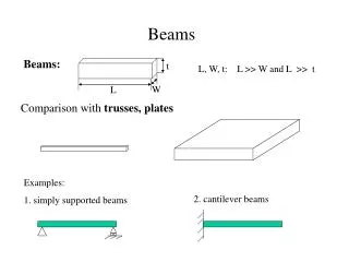
WORKSHEET 4 BEAMS
WORKSHEET 4 BEAMS. tributary area. 2m. 600mm. 600mm. Q1. Given that floor joists are at 600mm centres and span 2.0m between bearers, what is the tributary area for one joist?. tributary area for joist =. 2 x 0.6 =. 1.2 m 2. 6m. 6m. 6m. 6m. 6m. 6m. 6m. 6m. 6m. 6m. 6m.

WORKSHEET 4 BEAMS
E N D
Presentation Transcript
tributary area 2m 600mm 600mm Q1 Given that floor joists are at 600mm centres and span 2.0m between bearers, what is the tributary area for one joist? tributary area for joist = 2 x 0.6 = 1.2 m2
6m 6m 6m 6m 6m 6m 6m 6m 6m 6m 6m 6m Q2 Given a floor 18 m x 18 m with columns on a 6m x 6m grid, what is the tributary area for: (i) an internal column 6 x 6 = 36m2 (ii) a column on the edge 6 x 3 = 18m2 (ii) a corner column 3 x 3 = 9m2
6mm corrugated fibre cement sheet - 0.11kN/m2 100 x 50 hardwood rafters @ 600mm crs - 11 kN /m3 13mm plasterboard ceiling - 0.22kN/m2 0.6 1.67 1.67 x 0.6 = 1.0 Q3 Given the values in the Building Principles Notes for the Dead Loads of materials (P17), determine the dead load of the roof/ceiling construction shown below We are after a 1sq m of roof, but the rafters are at 600mm centres so that 1m width of roof will contain 1.67 rafters (1 / 0.6). Another way of doing this is to say that 1sqm can be achieved by an area 0.6 wide x 1.67 long (1 / 0.6). Weight of rafter 1.67m long = 0.1 x 0.05 x 1.67 x 11 = 0.09 kN Weight of 1 sq m fibre cement = 1 x 0.11 = 0.11 kN Weight of 1 sq m plasterboard = 1 x 0.22 = 0.22 kN Total weight of roof/ceiling per sq m = 0.42 kN / m2 = 0.42 kPa
2.5m 10.0m 2.5m 2.5m Q4 The roof above spans between roof trusses which are at 2.5 m centres and span 10m a) sketch the layout described and indicate the tributary area for one truss b) what is the total load on one truss?(neglecting the self-weight of the truss) Tributary area = 2.5 x 10 = 25 m2 Total load = 25 x 0.42 = 10.5 kN c) what is load per metre on one truss? Note: We have neglected the self-weight of the truss Load per metre = 10.5 / 10 =1.05kN / m
a) b) bending shear Q5 What are the two main types of stress involved in beam action?
a) b) which of the above two (bending & shear) is more important? why? Q6 In buildings: bending have bigger spans relative to loads. In the design of machines have short spans with heavy loads and shear more important.
a) b) c) timber beams? steel beams? concrete? Q7 What does shear force do to: can cause horizontal splitting along grain not so critical - make sure don’t exceed allowable shear stress tends to cause diagonal tension cracks near supports
Q8 How is shear resisted in concrete beams: a) steel reinforcement at 450 b) stirrups
a) b) What is the sign convention for Bending Moment Diagrams for: sagging? hogging? + - Q9 positive negative
a) What does a Shear Force Diagram tell you? b) What does a Bending Moment Diagram tell you? Q10 the values of the shear force along the beam you can see where the maximum shear force occurs the values of the bending moment along the beam you can see where the maximum bending moment occurs and whether it is positive or negative
a) b) c) d) Sketch the deflected shape and note where positive and negative bending moments are expected to occur Find the reactions Draw the Shear Force Diagrams Find the maximum bending moment(s) and draw the Bending Moment Diagrams Q11 For each of the Following Loading Conditions draw the diagrams approximately to scale (i.e. in proportion) and mark significant values make use of symmetry and standard Bending Moment coefficients where appropriate
A B 16 kN UDL 5kN/m 2m 4m 4m Deflected Shape + + 10 kN 10 kN 8 kN 8 kN +10 kN +8 kN SFD - 10 kN - 8 kN BMD +10 kNm wL2/8 = 5 x 4 x 4 / 8 = WL/4 = 16 x 4 / 4 = +16 kNm Q11 A & B
C D 10 kN UDL 5kN/m 2m 2m - - Deflected Shape W = w x L = 5 x 2 = 10 kN R =10 kN +10 kN +10 kN SFD -wL2/2 = -5 x 2 x 2 / 2 = -10 kNm BMD -WL = -20 kNm Q11 C & D
20kN 20kN 2m 2m 1m 5m +16 kN -4 kN SFD A B C D -24 kN + 16 kN 24 kN 24 kNm Deflected Shape 32 kNm BMD Q11 E TL = 20 + 20 = 40 kN For reactions Moments about A RR x 5 = 20 x 2 +20 x 4 = 120 RR = 24 kN RL = 16 kN Moment at B = 16 x 2 = 32 kNm Moment at C = 24 x 1 = 24 kNm
+15 kN 10kN 5kN +5 kN 1m 1m SFD 2m A B C - -20 kNm -5 kNm 15 kN Deflected Shape BMD Q11 F TL = 10 + 5 = 15 kN For reactions Moment at A = 10 x 1 + 5 x 2 = 20 kNm Moment at A = - 20 kNm Moment at B = - 5 x 1 = - 5 kNm
+12.5 kN 5kN 20kN SFD TL = 20 + 5 = 25 kN 2m 4m -5 kN For reactions Take Moment at C RL x 4 = 5 x 6 + 20 x 2 = 70 RL = 17.5kN RR = 7.5kN -7.5 kN A B C -10 kNm - 20 kNm + Deflected Shape 17.5 kN 7.5 kN +15 kNm BMD Q11 G Moment at A = -5 x 2 = -10 kNm Moment at B = 7.5 x 2 = 15kNm WL/4 = 20x4/4 = 20kNm
30kN UDL 5kN/m +12.5 kN 2m 4m SFD -7.5 kN A B C -10 kN -10 kNm 10kN 20kN - 10 kNm Deflected Shape + +5 kNm 22.5 kN 7.5 kN +~5.6 kNm BMD Q11 H TL = 5 x 6 = 30 kN For reactions Take Moment at C RL x 4 = 30 x 3 = 90 RL = 22.5kN RR = 7.5kN Moment at A = -10 x 1 = -10 kNm Moment at B = 7.5 x 2 - 5 x 2 x 1 = 15 - 10 = 5 kNm WL/8 = 20x4/8 = 10kNm
-10 kNm BMD (cantilever) wL2/2 = -10 kNm BMD (Simply Supported) +10 kNm wL2/8 = 10 kNm BMD(Comb) -10 kNm ~+5.6 kNm Q11 H (cont.)
UDL 5kN/m +10 kN 2m 4m 2m SFD (Cantilevers) 10kN 10kN - - Cantilevers -10 kN RL = 10 RR = 10 +10 kN SFD (Simply Supported) 10 kN 10 kN Simply Supported 20kN RL = 10 RR = 10 -10 kN + 10 kN 10 kN +10 kN +10 kN 20kN 10kN 10kN SFD (Combined) Combined - - RL = 20 RR = 20 20 kN 20 kN -10 kN -10 kN Q11 I
-10 kNm BMD (cantilevers) BMD (Simply Supported) +10 kNm -10 kNm -10 kNm BMD(Comb) Q11 I (cont.) wL2 / 2 = 5 x 2 x 2 / 2 = 10 kNm wL2 / 8 = 5 x 4 x 4 / 8 = 10 kNm