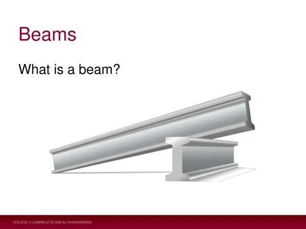
Beams
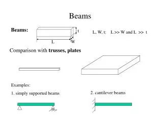
Beams. Beams:. t. L, W, t: L >> W and L >> t. W. L. Comparison with trusses, plates. Examples:. 2. cantilever beams. 1. simply supported beams. Beams - loads and internal loads. Loads: concentrated loads, distributed loads, couples (moments).


Beams
E N D
Presentation Transcript
Beams Beams: t L, W, t: L >> W and L >> t W L Comparison with trusses, plates Examples: 2. cantilever beams 1. simply supported beams
Beams - loads and internal loads Loads: concentrated loads, distributed loads, couples (moments) Internal loads: shear force and bending moments
Shear Forces, Bending Moments - Sign Conventions right section left section Shear forces: positive shear: negative shear: Bending moments: positive moment negative moment
Shear Forces, Bending Moments - Static Equilibrium Approach Procedure: 1. find reactions; 2. cut the beam at a certain cross section, draw F.B.D. of one piece of the beam; 3. set up equations; 4. solve for shear force and bending moment at that cross section; 5. draw shear and bending moment diagrams. Example 1: Find the shear force and bending diagram at any cross section of the beam shown below.
Relationship between Loads, Shear Forces, and Bending Diagram
Beam - Normal Strain M M no transverse load Pure bending problem no axial load no torque Observations of the deformed beam under pure bending Length of the longitudinal elements Vertical plane remains plane after deformation Beam deforms like an arc
Normal Strain - Analysis neutral axis (N.A.): radius of curvature: Coordinate system: q longitudinal strain: r y N.A.
Beam - Normal Stress Hooke’s Law: y M M M x Maximum stresses: Neutral axis:
Flexure Formula y Moment balance: M x Comparison: Axially loaded members Torsional shafts:
Moment of Inertia - I Example 2: h w Example 3: h w w 4h w
Design of Beams for Bending Stresses Design Criteria: 1. 2. cost as low as possible Design Question: Given the loading and material, how to choose the shape and the size of the beam so that the two design criteria are satisfied?
Design of Beams for Bending Stresses Procedure: • Find Mmax • Calculate the required section modulus • Pick a beam with the least cross-sectional area or weight • Check your answer
Design of Beams for Bending Stresses Example 4: A beam needs to support a uniform loading with density of 200 lb /ft. The allowable stress is 16,000 psi. Select the shape and the size of the beam if the height of the beam has to be 2 in and only rectangular and circular shapes are allowed. 6 ft
Shear Stresses inside Beams shear force: V V Horizontal shear stresses: y h1 y1 x h2 s2 s1 tH
Shear Stresses inside Beams Relationship between the horizontal shear stresses and the vertical shear stresses: y h1 y1 x h2 Shear stresses - force balance V: shear force at the transverse cross section Q: first moment of the cross sectional area above the level at which the shear stress is being evaluated w: width of the beam at the point at which the shear stress is being evaluated I: second moment of inertial of the cross section
Shear Stresses inside Beams Example 5: Find shear stresses at points A, O and B located at cross section a-a. P a A O a B w
Shear Stress Formula - Limitations - elementary shear stress theory Assumptions: 1. Linearly elastic material, small deformation 2. The edge of the cross section must be parallel to y axis, not applicable for triangular or semi-circular shape 3. Shear stress must be uniform across the width 4. For rectangular shape, w should not be too large
Shear Stresses inside Beams Example 6: The transverse shear V is 6000 N. Determine the vertical shear stress at the web.
Beams - Examples Example 7: For the beam and loading shown, determine (1) the largest normal stress (2) the largest shearing stress (3) the shearing stress at point a
Deflections of Beam Deflection curve of the beam: deflection of the neutral axis of the beam. y P y x x Derivation: Moment-curvature relationship: Curvature of the deflection curve: (1) (2) Small deflection: (3) Equations (1), (2) and (3) are totally equivalent.
Deflections by Integration of the Moment Differential Equation Example 8 (approach 1):
Deflections by Integration of the Load Differential Equation Example 8 (approach 2):
Method of Superposition P q Deflection: y P Deflection: y2 Deflection: y1
Method of Superposition Example 9
Statically Indeterminate Beam Number of unknown reactions is larger than the number of independent Equilibrium equations. Propped cantilever beam Clamped-clamped beam Continuous beam
Statically Indeterminate Beam Example 10. Find the reactions of the propped beam shown below.