Download
1 / 22
220 likes | 364 Vues
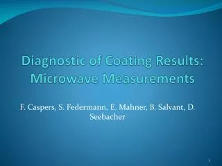
Measurement of Electromagnetic properties of NEG coating in the microwave range. David Seebacher Status current experience Potential explanation of causes and effects observed Could NEG be a very high ε dielectric in the microwave range Microwave bench measurements done so far

E N D
Measurement of Electromagnetic properties of NEG coating in the microwave range David Seebacher Status current experience Potential explanation of causes and effects observed Could NEG be a very high ε dielectric in the microwave range Microwave bench measurements done so far Description and justification of the proposed measurement method Expected results David Seebacher , NEG properties in the microwave range, SPSU Meeting, 17th February, CERN
NEG Coating @ ELETTRA:4 Years Of Experience David Seebacher , NEG properties in the microwave range, SPSU Meeting, 17th February, CERN
Impact of NEG Coating on the Impedance Considerable impact on imaginary part of transverse impedance due to NEG Impact of NEG Coating on the Impedance 11th ESLS Workshop, 17 ~ 18 November 2003, ESRF, Grenoble By Ryutaro Nagaoka, Synchrotron SOLEIL David Seebacher , NEG properties in the microwave range, SPSU Meeting, 17th February, CERN
Comparison of different vacuum chambers Impact of NEG Coating on the Impedance 11th ESLS Workshop, 17 ~ 18 November 2003, ESRF, Grenoble By Ryutaro Nagaoka, Synchrotron SOLEIL This reference claims a serious impact on the imaginary part of the transverse impedance due to NEG coating Surface impedance is proportional (1+j), real part is not considered here David Seebacher , NEG properties in the microwave range, SPSU Meeting, 17th February, CERN
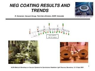
NEG-COATED VACUUM CHAMBERS AT THE ESRF No adverse effect on the impedance of the machine caused by the electric conductivity of the NEG coatings has been noticed [4]. One of our colleagues, --E. Plouviez of the Diagnostic Group, Machine Division-- has measured the surface resistance of sample kapton foils which had been coated by us (thicknesses measured: 0.6 and 2 μm). At the chosen frequency of 14 GHz a resistivity of 5.0E-6 Ω/m has been measured. This means that the skin-depth at 14 GHz is greater than the NEG-coating thickness [7]. This reference: no adverse effects NEG-COATED VACUUM CHAMBERS AT THE ESRF: PRESENT STATUS AND FUTURE PLANS R. Kersevan, ESRF, Grenoble David Seebacher , NEG properties in the microwave range, SPSU Meeting, 17th February, CERN
Bench measurement method (1) MEASUREMENT OF THE RESISTIVITY OF THE NEG COATING AT 14 GHz Diagnostics 02-03 E. Plouviez 21/04/2002 ---------------------------------------------------------------------------------------------------------------- NEG resistivity measurement We have measured the surface resistance at 14 GHz of samples of kapton coated with NEG. The coating process is the same as the one that will be used for the ESRF low gap straight section vacuum vessel. The thickness of the coating of the samples was about .6 mm and 2 mm; the coating of the vacuum vessel will be 2 mm thick. Measurement method We have inserted the samples between the flanges of two X band wave guide to N type connectors transitions. The cross section of the wave guide is 22.5 X 10.5mm. We have measured the reflection and transmission coefficient of the films, called s11 and s21 using the usual RF measurement notation, For this measurement , we have used a HP8510 vector network analyzer; in this way we can obtain the value of the complex impedance of the NEG coated kapton films normalized by the wave guide impedance Z0= 330Ω. • Open questions: • Z0=waveguide impedance =330Ω? Waveguide impedance for TE10 Mode always bigger then 377Ω • Measurement at 14GHz? Frequency range of X-Band is 8.2 to 12.4 GHz, at 14GHz the TE20 mode can already propagate David Seebacher , NEG properties in the microwave range, SPSU Meeting, 17th February, CERN
Bench measurement method (2) s11 =Z- Z0/Z+ Z0 => Z/ Z0=1+ s11/1- s11 In our case Z is real since the film impedance is purely resistive, so s11 and s21 are real. When s11 is close to 1 this Z derivation can be inaccurate; in this case it is better to use the s21 measurement of the transmitted signal through the film. When a transmission line is terminated by a an impedance much lower than Z0 the current flowing in this termination will be equal to the sum of the current corresponding to the incident signal and the reflected signal. For an incident signal power Pi we can we write: P i= ½ Vi2/ Z0 or Pi= ½ Z0 Ii2 and for the reflected signal power we have: Pr= ½ Z0 Ir2 Since in the case of a very low impedance termination such as our NEG film, the reflected signal amplitude is nearly equal to the incident signal amplitude, the current (Ii +Ir) flowing in the termination is about twice the incident signal current, the voltage across this impedance Z is: V= Z.(Ii +Ir). David Seebacher , NEG properties in the microwave range, SPSU Meeting, 17th February, CERN
Bench measurement method (3) Then the transmitted power Pt is equal to: Pt= ½V2/ Z0 Pt= ½ (( Ii +Ir)Z)2/ Z0 =1/2 ( 2.Ii .Z)2/ Z 0 for s11 close to 1 The ratio Pt / Pi is equal to s212 and we will have Z/ Z0 = s21/2 Measurement results For the first .6mm thick sample we measured s11 = -.97 and s21 = .1 and for the second 2mm thick sample we measured s11 = -.98 and s21 = .03 Z0= 330 Ω so the .6mm thick sample resistance is 16.5 Ω and the 2 mm thick sample resistance is 5 Ω at 14GHz. The current is flowing between the large sides of the waveguide; so the surface resistances of the films are about 33 Ω /square and 10 Ω /square So the resistivity of the coating seems to be about 2.5 10-5Ω.m and the coating is still much thinner than the skin depth at 14 GHz: good news! David Seebacher , NEG properties in the microwave range, SPSU Meeting, 17th February, CERN
Bench measurement Setup • The sample foil is placed in the middle and the reflection due to the properties of the sample are measured • Method is not able to determine whether the sample is a conductor or has a very high ε, which show both the same effect strong coupling on both ports, sample foil placed in the middle David Seebacher , NEG properties in the microwave range, SPSU Meeting, 17th February, CERN
2 Layer conductor • A thin layer with high resistance on a good conducting material has little influence on the overall impedance • As long as the skindepth is large with respect to the layer thickness • Skindepth @3GHz for NEG ~20 µm (ρ=500e-8 Ωm) H. Meinke and F.W. Gundlach, TaschenbuchderHochfrequenztechnik, Springerverlag Berlin 1968 David Seebacher , NEG properties in the microwave range, SPSU Meeting, 17th February, CERN
Study of resistive wall effects on SOLEIL • Calculations correspond with theory of slide before • As the resistivity of the surface layer is increased the impact is limited(saturation) • As the thickness is increased the NEG-layer gets the main conductor and impedance increases to that of NEG Study of Resistive-Wall effects on SOLEIL, EPAC 2004 By Ryutaro Nagaoka, Synchrotron SOLEIL David Seebacher , NEG properties in the microwave range, SPSU Meeting, 17th February, CERN
Study of resistive wall effects on SOLEIL • To explain the observations at ELETTRA ρ has to be bigger than 500E-8 and the coating has to be thicker than 10µm (calculations done at 2GHz) • The studies can’t explain the high increase observed at ELETTRA Study of Resistive-Wall effects on SOLEIL, EPAC 2004 By Ryutaro Nagaoka, Synchrotron SOLEIL David Seebacher , NEG properties in the microwave range, SPSU Meeting, 17th February, CERN
Summary of statements David Seebacher , NEG properties in the microwave range, SPSU Meeting, 17th February, CERN
Possible reasons • A possibility is that higher spectral frequencies (~100 GHz) can’t be neglected and cause a major part of the impedance increase (skindepth isn’t anymore larger than the layer thickness) • The increase of the imaginary part could be related a very high dielectric constant of NEG at microwave frequencies, which we want to test with the following experiment, in other words we want to test the hypothesis that NEG appears as a very high dielectric beyond say one GHz • For SPS only we are interested only in frequencies up to about 3GHz, however measurements in electron machines are done with short bunches with spectral components well beyond 100GHz David Seebacher , NEG properties in the microwave range, SPSU Meeting, 17th February, CERN
Cavity transmission resonator • The resonator is measured in transmission S21 • For our measurement a rectangular S-Band (2-4GHz) TE103 resonator will be used weakly coupled at input- and output- port, thus the measured Q is approximately equal to the unloaded Q David Seebacher , NEG properties in the microwave range, SPSU Meeting, 17th February, CERN
Field in the resonator • The sample is inserted at the maximum of the electric field in the middle of the resonator • As long as the sample is small we can assume that the field isn’t disturbed it will just detune the resonator • The measurement on metal is difficult, therefore we use a glass rod for this purpose Sample (4mm diameter glass rod), reference measurement uncoated David Seebacher , NEG properties in the microwave range, SPSU Meeting, 17th February, CERN
Resonance peaks Resonance peaks • There are resonances whenever half of the guided wavelength is a multiple of the length of the resonator • Only the odd peaks (TE103, TE105…)will be detuned because for the even ones there is no electric field at the sample so it has is no influence below cut-off David Seebacher , NEG properties in the microwave range, SPSU Meeting, 17th February, CERN
Determination of resonance frequency • The resonant frequency f0 is the center frequency of the peak • The -3db bandwidth is the difference between the two points where the -3db line intersects the 0db -3db Fo = f1 f2 f0 David Seebacher , NEG properties in the microwave range, SPSU Meeting, 17th February, CERN
, . Q-factor • The Quality factor is defined as the center frequency over the Bandwidth • The bandwidth is measured at -3db (0.707) and refers to the point where only half of the power is transferred • The narrower the f1 and f2 are the higher the Q-factor is • The dielectric loss in the sample will change the Q-factor David Seebacher , NEG properties in the microwave range, SPSU Meeting, 17th February, CERN
Determination of the permittivity • To determine the permittivity two measurements are required • One with the empty resonator as reference (In our case with uncoated glass rods) • One with the perturbation resonator (coated glass rods) • From the frequency shift and the change of the Q factor or the change of power loss we can determine the complex permittivity David Seebacher , NEG properties in the microwave range, SPSU Meeting, 17th February, CERN
Change of Resonant Frequency • For a dielectric sample the resonant frequency will decrease • For a conducting sample the resonant frequency will increase dielectric conductor Increase of resonant frequency due to the inserted wire David Seebacher , NEG properties in the microwave range, SPSU Meeting, 17th February, CERN
Preliminary conclusion • Different partly contradictory statements about the Impedance of NEG • With the resonator measurement we can determine whether NEG is a bad conductor or a bad dielectric • We expect to measure a high ε in order to explain the effects observed David Seebacher , NEG properties in the microwave range, SPSU Meeting, 17th February, CERN