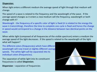
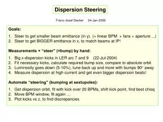
Dispersion Steering
Dispersion Steering. Franz-Josef Decker 24-Jan-2005. Goals: Steer to get smaller beam emittance (in y). (+ linear BPM + fans + aperture ...) 2. Steer to get BIGGER emittance in x, to match beams at IP! Measurements + “steer” (=bump) by hand:

Dispersion Steering
E N D
Presentation Transcript
Dispersion Steering Franz-Josef Decker 24-Jan-2005 • Goals: • Steer to get smaller beam emittance (in y). (+ linear BPM + fans + aperture ...) • 2. Steer to get BIGGER emittance in x, to match beams at IP! • Measurements + “steer” (=bump) by hand: • Big x-dispersion kicks in LER arc 7 and 9 (22-Jul-2004) • Fit necessary kicks, calculate required bump size, compare to absolute orbit • Luminosity goes down (5-10%), tune back up and more with bumps 90 away • Measure dispersion at high current and get even bigger dispersion beats! • Automate “steering” (bumping at sextupoles): • Get dispersion orbit, fit with kick over 20 BPMs, shift kick point, find best chisq • Move BPM window, fit again … • Plot kicks vs z, to find discrepancies
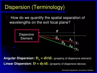
LER Dispersion Orbit from Characterization of 24-Jun-2004 (low current)
Quantifying Orbit Bumps with Kicks • LER in arc 9 to arc 7 has an x-dispersion beat (like the HER). • It can be fitted at special locations to the following value and compared to real absolute BPM reading (like BBA!): • Bumps in x at Bumps from fitted kicks BPM reading • 4142 / 4102 in PR06 SF2 -/+ 2.0 mm -2.3/+2.0 mm • 1142 / 1102 in PR10 SF1 +/- 4.4 mm +4.9/-4.7 mm • Calculate: • 11 urad at 1102 in x SF2 = 377 kG/m SF1 = 188.5 kG/m • Kick angle: = l/= 0.03 B[kG] l[m]/p[GeV/c] l = length • Bl [kG-m] = p[GeV/c] /0.03 = 104 for LER • or 0.011 mrad gets 0.00114 kG-m or half of that at each sextupole of a pair • 2 * 188.5 kG/m *0.7 mm * x = 0.00114 kG-m x = 4.32 mm • (0.7 mm is the orbit due to the energy change) • In PR06 SF2 is twice as strong requiring a smaller kick • 5. Two arcs with dispersion beat up to 0.9 m increase emittance up to 27.5 nm
LER Dispersion Orbit at High Current (+/- 200 Hz E = 0.66 ‰) (after 2.0 and 4.4 mm bumps and tuning at 90 away)
Also Correctors closer to zero after bumps and Luminosity up
Additional Bumps to Raise Lifetime from 27 to 48 min, reducing main losses in PR08 All done at the end of run instead of preparing talk for close out.
Results from Fitting • Arc 7 and 9 show bigger x kicks • Some x-kicks are at the chicane magnets • (Trick to avoid bad BPMs: minimize RMS after sorting first all BPM differences and ignore the biggest 10%) Problems so far • Some kicks end up at QDs with a bigger value • Kicks in x and y are “coupled” to be at the same point separate • How to “fix” a kick generated at a chicane magnet? • Kicks are now at every “BPM”, which gives 0, 45, 90,135, 180, … • so part at 0 and part at 90 giving 30 is not well treated • 5. Some regions show still bad fitting (many orbits visible)