Projection Matrix Tricks Eric Lengyel
460 likes | 772 Vues
Projection Matrix Tricks Eric Lengyel. Outline. Projection Matrix Internals Infinite Projection Matrix Depth Modification Oblique Near Clipping Plane Slides available at http://www.terathon.com/. From Camera to Screen. Camera Space. Projection Matrix. Homogeneous Clip Space.

Projection Matrix Tricks Eric Lengyel
E N D
Presentation Transcript
Outline • Projection Matrix Internals • Infinite Projection Matrix • Depth Modification • Oblique Near Clipping Plane • Slides available at http://www.terathon.com/
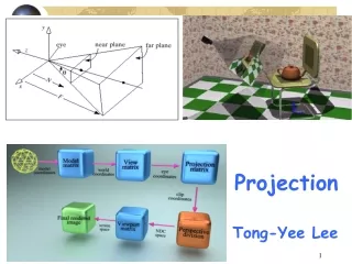
From Camera to Screen CameraSpace Projection Matrix HomogeneousClip Space Perspective Divide Normalized Device Coordinates Viewport Transform Viewport Coordinates
Projection Matrix • The 4×4 projection matrix is really just a linear transformation in homogeneous space • It doesn’t actually perform the projection, but just sets things up right for the next step • The projection occurs when you divide by w to get from homogenous coordinates to 3-space
OpenGL projection matrix • n, f = distances to near, far planes • e = focal length = 1 / tan(FOV / 2) • a = viewport height / width
Infinite Projection Matrix • Take limit as f goes to infinity
Infinite Projection Matrix • Directions are mapped to points on the infinitely distant far plane • A direction is a 4D vector with w = 0 (and at least one nonzero x, y, z) • Good for rendering sky objects • Skybox, sun, moon, stars • Also good for rendering stencilshadow volume caps
Infinite Projection Matrix • The important fact is that z and w are equal after transformation to clip space:
Infinite Projection Matrix • After perspective divide, thez coordinate should be exactly 1.0, meaning that the projected point is precisely on the far plane:
Infinite Projection Matrix • But there’s a problem... • The hardware doesn’t actually perform the perspective divide immediately after applying the projection matrix • Instead, the viewport transformation is applied to the (x, y, z) coordinates first
Infinite Projection Matrix • Ordinarily, z is mapped from the range [−1, 1] in NDC to [0, 1] in viewport space by multiplying by 0.5 and adding 0.5 • This operation can result in a loss of precision in the lowest bits • Result is a depth slightly smaller than 1.0 or slightly bigger than 1.0
Infinite Projection Matrix • If the viewport-space z coordinate is slightly bigger than 1.0, then fragment culling occurs • The hardware thinks the fragments are beyond the far plane • Can be corrected by enabling GL_DEPTH_CLAMP_NV, but this is a vendor-specific solution
Infinite Projection Matrix • Universal solution is to modify projection matrix so that viewport-space z is always slightly less than 1.0 for points on the far plane:
Infinite Projection Matrix • This matrix still maps the near planeto −1, but the infinite far plane is now mapped to 1 − e
Infinite Projection Matrix • Because we’re calculating e − 1 ande − 2, we need to choose so that 32-bit floating-point precision limits aren’t exceeded
Depth Modification • Several methods exist for performing polygon offset • Hardware support through glPolygonOffset • Fiddle with glDepthRange • Tweak the projection matrix
Depth Modification • glPolygonOffset works well, but • Can adversely affect hierarchicalz culling performance • Not guaranteed to be consistent across different GPUs • Adjusting depth range • Reduces overall depth precision • Both require extra state changes
Depth Modification • NDC depth is given by a function ofthe lower-right 2×2 portion of the projection matrix:
Depth Modification • We can add a constant offset e to the NDC depth as follows:
Depth Modification • w-coordinate unaffected • Thus, x and y coordinates unaffected • z offset is constant in NDC • But this is not constant in camera space • For a given offset in camera space, the corresponding offset in NDC depends on the depth
Depth Modification • What happens to a camera-spaceoffset d ?
Depth Modification • NDC offset as a function of camera-space offset d and camera-space z: • Remember, d is positive for anoffset toward camera
Depth Modification • Need to make sure that e is big enough to make a difference in a typical 24-bit integer z buffer • NDC range of [−1,1] is divided into224 possible depth values • So |e| should be at least 2/224 = 2−23
Depth Modification • But we’re adding e to (f + n)/(f − n), which is close to 1.0 • Not enough bits of precision in 32-bit float for this • So in practice, it’s necessary to use
Oblique Near Clipping Plane • It’s sometimes necessary to restrict rendering to one side of some arbitrary plane in a scene • For example, mirrors and water surfaces
Oblique Near Clipping Plane • Using an extra hardware clipping plane seems like the ideal solution • But some older hardware doesn’t support user clipping planes • Enabling a user clipping plane could require modifying your vertex programs • There’s a slight chance that a user clipping plane will slow down your fragment programs
Oblique Near Clipping Plane • Extra clipping plane almost always redundant with near plane • No need to clip against both planes
Oblique Near Clipping Plane • We can modify the projection matrix so that the near plane is moved to an arbitrary location • No user clipping plane required • No redundancy
Oblique Near Clipping Plane • In NDC, the near plane hascoordinates (0, 0, 1, 1)
Oblique Near Clipping Plane • Planes are transformed from NDC to camera space by the transpose of the projection matrix • So the plane (0, 0, 1, 1) becomesM3 + M4, where Mi is the i-th row of the projection matrix • M4 must remain (0, 0, −1, 0) so that perspective correction still works right
Oblique Near Clipping Plane • Let C = (Cx, Cy, Cz, Cw) be the camera-space plane that we want to clip against instead of the conventional near plane • We assume the camera is on the negative side of the plane, so Cw < 0 • We must have C = M3 + M4, whereM4 = (0, 0, −1, 0)
Oblique Near Clipping Plane • M3 = C − M4 = (Cx, Cy, Cz + 1, Cw) • This matrix maps points on the plane C to the z = −1 plane in NDC
Oblique Near Clipping Plane • But what happens to the far plane? • F = M4 − M3 = 2M4 − C • Near plane and far plane differ only in the z coordinate • Thus, they must coincide where they intersect the z = 0 plane
Oblique Near Clipping Plane • Far plane is completely hosed!
Oblique Near Clipping Plane • Depths in NDC no longer represent distance from camera plane, but correspond to the position between the oblique near and far planes • We can minimize the effect,and in practice it’s not so bad
Oblique Near Clipping Plane • We still have a free parameter:the clipping plane C can be scaled • Scaling C has the effect of changing the orientation of the far plane F • We want to make the new view frustum as small as possible while still including the conventional view frustum
Oblique Near Clipping Plane • Let F = 2M4 − aC • Choose the point Q which lies furthest opposite the near plane in NDC: • Solve for a such that Q lies in plane F (i.e., F·Q = 0):
Oblique Near Clipping Plane • Near plane doesn’t move, but far plane becomes optimal
Oblique Near Clipping Plane • This also works for infinite view frustum • Far plane ends up being parallel to one of the edges between two side planes • For more analysis, see Journal of Game Development, Vol 1, No 2
Questions? • lengyel@terathon.com