Download
1 / 78
790 likes | 1.24k Vues
Lecture 10 Multi-Spectral Remote Sensing Systems 14 October 2008. Reading Assignment. Campbell, Chapters 6, 21 Note: Most of the figures and tables from today’s lecture are from Jensen’s Introduction to Remote Sensing. Lecture Topics. Measuring radiance

E N D
Lecture 10Multi-Spectral Remote SensingSystems14 October 2008
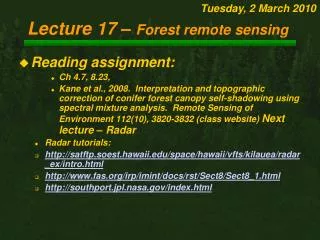
Reading Assignment • Campbell, Chapters 6, 21 Note: Most of the figures and tables from today’s lecture are from Jensen’s Introduction to Remote Sensing
Lecture Topics • Measuring radiance • Key questions for designing spaceborne radiometers • Considerations for deploying a spaceborne radiometer • Problems in imaging over wide swaths • Summary of system tradeoffs categories of satellite radiometers • Types and key features of multi-spectral scanning systems • Key Spaceborne Remote Sensing Systems • Land Surface Remote Sensing • Water Surface Remote Sensing
Radiometers and Spectrometers • Radiometer –An instrument that measures radiance in a specified wavelength region • Spectroradiometer or spectrometer –An instrument that measures radiance continuously across a region of the EM spectrum or in multiple-bands across a region of the EM spectrum
Fig. 1 Radiance (W/sq m/sr)
Fig. 2 Radiance (W/sqm/sr)
Lecture Topics • Measuring radiance • Key questions for designing spaceborne radiometers • Considerations for deploying a spaceborne radiometer • Problems in imaging over wide swaths • Summary of system tradeoffs categories of satellite radiometers • Types and key features of multi-spectral scanning systems • Key Spaceborne Remote Sensing Systems • Land Surface Remote Sensing • Water Surface Remote Sensing
Questions to ask when designing a multi-channel spaceborne radiometer • What reflectance characteristics are you trying to measure? Spectral resolution • How precisely do you have to measure radiance in order to be able to discriminate or measure the features of interest? Radiometric resolution • How large are the features of interest? Spatial resolution and swath width • How frequently and when do you have to measure the features of interest? Temporal resolution and swath width
Resolution • Spectral Resolution – the wavelength regions of and bandwidths for a radiometer • Radiometric Resolution - the sensitivity of a remote sensing detector to variations in the emitted, reflected or scattered EM energy that is being detected • Spatial Resolution - The measure of the smallest distance (linear or angular separation) between objects that can be resolved by the sensor • Temporal Resolution – the timing and frequency for collection of data by a satellite system
Vegetation Geology/Soils Spectral Resolution Sensors are designed to contain spectral bands specific to the type of surface feature being monitored or mapped Fig. 3
Fig. 4 Radiometric Resolution If our system was designed to detect radiance values between 0 and 0.0015 watts/sq m, and we had 8 bit recording (0 to 255), then the radiometric resolution would be 0.0000006 watts/sq m
Spatial Resolution is determined by the Instantaneous Field of View- IFOV • All scanning radiometers have an instantaneous field of view over which the sensor detects EM energy for a specific pixel
Fig. 5 Sensor IFOV (in degrees, ) H r Radius of circle within IFOV, r = H tan /2 For very small IFOV, e.g., <<< 0.01º, r = H /2, where is in radians
Changes in IFOV • If you are imaging over a very wide swath, then H will increase as you scan away from nadir, meaning the size of the IFOV on the ground will increase
Temporal Resolution Temporal resolution has three important components – • How frequently you have to observe a specific area on the earth’s surface to capture variations over time of the phenomena being observed • When during the year do the phenomena you are interested in take place • The diurnal (e.g., 24 hour) variations in the signature being observed • Variations in solar illumination • Variations in the occurrence of the phenomena • Variations in characteristics of the atmosphere
Swath Width • How large of an area does the remote sensing system have to capture in order to collect data about the features or processes of interest? • Swath widths of satellite remote sensing systems range between 7 and 2,500 kilometers • Swath width + the orbital path of the satellite determine temporal resolution
Lecture Topics • Measuring radiance • Key questions for designing spaceborne radiometers • Considerations for deploying a spaceborne radiometer • Problems in imaging over wide swaths • Summary of system tradeoffs categories of satellite radiometers • Types and key features of multi-spectral scanning systems • Key Spaceborne Remote Sensing Systems • Land Surface Remote Sensing • Water Surface Remote Sensing
CONSIDERATIONS FOR SATELLITE DEPLOYMENT OF A RADIOMETER • What is the size of the area or patch being detected by the satellite radiometer? • How frequently can a satellite view the same piece of ground on the earth’s surface? • How large an area is imaged by the sensor? • How much data are being recorded by the radiometer and how do we retrieve these data? • How do variations in surface and atmospheric conditions affect the data quality?
CONSIDERATIONS FOR SATELLITE DEPLOYMENT OF A RADIOMETER • What is the size of the area or patch being detected by the satellite radiometer? Determined by • The IFOV of the sensor • The height of the satellite platform • The scanning angles of the radiometer
CONSIDERATIONS FOR SATELLITE DEPLOYMENT OF A RADIOMETER • What is the size of the patch being detected by the satellite? • How frequently can a satellite view the same piece of ground on the earth’s surface? • How large of an area is imaged by the sensor? • How much data are being recorded by the radiometer and how do we retrieve these data? • How do variations in surface and atmospheric conditions affect the data quality? • How do you record/transmit the data being detected/recorded by the systems
Controls on Frequency of Coverage by a Satellite (temporal resolution) • The orbital time of the satellite • The width of the area being imaged by a satellite when it passes over the earth
A satellite in low earth orbit (~800 km) takes about 90 minutes to complete a single passage from equator to equator Fig. 6
Atmospheric Conditions • In most regions with significant vegetation, there is a diurnal variation in atmospheric moisture and cloud cover that is driven by evapo-transpiration by plants • Cloud cover is lowest in the early morning hours, then increases as the day progresses • In many areas, the resulting cloud formation hinders viewing of the earth’s surfaces over land areas by the early afternoon • Because of this, many sensors schedule fly-over times between 10 am and noon
Earth’s circumference = 39,350 km At 800 km, the satellite has 16 orbits per day at 90 minutes per orbit 39,350 km / 16 = 2,460 km per orbit Question – how big of a swath does a satellite need to image the earth’s surface once per day when the sun is out?
Question – if a satellite has a swath width of 172 km, how long does it take to image the entire earth’s surface? 16 orbits per day Total area covered per day is 16 x 176 = 2,816 km Covering the entire earth: (39,350 km) / (2,816 km/day) = 14 days
CONSIDERATIONS FOR SATELLITE DEPLOYMENT OF A RADIOMETER • What is the size of the patch being detected by the satellite? • How frequently can a satellite view the same piece of ground on the earth’s surface? • How large an area is imaged by the sensor? • How much data are being recorded by the radiometer and how do we retrieve these data? • How do variations in surface and atmospheric conditions affect the data quality?
Approaches to Recover Data from Satellite Remote Sensing Systems • Ground receiving station within direct view of the satellite (to acquire global coverage requires a large number of stations) • On-board data recorders (requires reliable, large volume recorders) for delayed transmission to ground receiving station • Using data relay satellites – e.g., the TDRSS - Tracking and Data Relay Satellite System
Wide Swath / Low Resolution Narrow Swath/ High Resolution Image Size 2460 by 2460 km 172 by 172 km Ground area size (resolution or pixel size) 1 by 1 km 0.05 by 0.05 km (50 by 50 m) Number of radiometer channels 4 4 Images per orbit 16 228.8 Pixels per image per channel 6 million 11.8 million Pixels per orbit per channel 96 million 2.7 billion Pixels per orbit for all channels 384 million 10.8 billion High resolution, wide swath – pixels per orbit for all channels 155 billion Data per day 2.5 trillion Data per month 743 trillion
Lecture Topics • Measuring radiance • Key questions for designing spaceborne radiometers • Considerations for deploying a spaceborne radiometer • Problems in imaging over wide swaths • Summary of system tradeoffs categories of satellite radiometers • Types and key features of multi-spectral scanning systems • Key Spaceborne Remote Sensing Systems • Land Surface Remote Sensing • Water Surface Remote Sensing
CONSIDERATIONS FOR SATELLITE DEPLOYMENT OF A RADIOMETER • What is the size of the patch being detected by the satellite? • How frequently can a satellite view the same piece of ground on the earth’s surface? • How large an area is imaged by the sensor? • How much data are being recorded by the radiometer and how do we retrieve these data? • How do variations in surface and atmospheric conditions affect the data quality?
Problems with imaging over wide swaths • The size of your ground footprint gets bigger as the angle off nadir increases • Atmospheric effects increase • The bidirectional reflectance at the surface often changes, e.g., the emittance from the surface for the same surface cover type changes
Problems with imaging over wide swaths • The size of your ground footprint gets bigger as the angle off nadir increases • Atmospheric effects increase because of the increase in path length through the atmosphere • The bidirectional reflectance at the surface often changes, e.g., the emittance from the surface for the same surface cover type changes
Atmospheric effects • Effects of atmosphere on incoming/outgoing EM energy is proportional to distance traveled through the atmosphere • As incidence angle increases, atmospheric effects (scattering, absorption, attenuation) increase • Using wide swath width increases the requirements for atmospheric correction of the data
Problems with imaging over wide swaths • The size of your ground footprint gets bigger as the angle off nadir increases • Atmospheric effects increase • The bidirectional reflectance at the surface often changes, e.g., the emittance from the surface for the same surface cover type changes
Lecture Topics • Measuring radiance • Key questions for designing spaceborne radiometers • Considerations for deploying a spaceborne radiometer • Problems in imaging over wide swaths • Summary of system tradeoffs Categories of satellite radiometers • Types and key features of multi-spectral scanning systems • Key Spaceborne Remote Sensing Systems • Land Surface Remote Sensing • Water Surface Remote Sensing
Narrow-Swath, Higher Resolution Wide-Swath, Lower Resolution (-) Coverage only every 15 to 20 days (less if cloud cover exists) (+) Daily coverage of area (+) High resolution imagery (-) Low resolution imagery (-) Higher data volumes requires on-board recording or direct transmission (+) Lower data volumes result in less stringent recording/direct transmission requirements (+) Narrow viewing angle results in lower atmospheric / bi-directional scattering effects, and consistent across-swath resolution (-) Wider viewing angle results in greater atmospheric / bi-directional scattering effects, and variable across-swath resolution Summary of System Tradeoffs (+) advantage, (-) disadvantage
Categories of satellite radiometers • Wide swath, low resolution • 1000-2600 km swath, 250 to 1100 m • Moderate swath, moderate resolution • 100 to 200 km swath, 10 to 50 m resolution • Narrow swath, fine resolution • 5 to 15 km swath, 1 to 4 m resolution
Lecture Topics • Measuring radiance • Key questions for designing spaceborne radiometers • Considerations for deploying a spaceborne radiometer • Problems in imaging over wide swaths • Summary of system tradeoffs categories of satellite radiometers • Types and key features of multi-spectral scanning systems • Key Spaceborne Remote Sensing Systems • Land Surface Remote Sensing • Water Surface Remote Sensing
Types of VIS/RIR scanning systems • Multispectral scanners –scanning systems that detect and record reflected, emitted or backscattered energy from an area of interest in a limited number of broad bands of the electromagnetic spectrum • Hyperspectral scanners –scanning systems identical to multispectral scanners, except they detect and record energy from hundreds of narrow bands of the electromagnetic spectrum
First Spaceborne MSS SatelliteEarth Resources Technology Satellite – ERTS-1 (Changed later to Landsat 1) • Launched 23 July 1972 • Contained two systems • 3 Channel Return Beam Vidicom (RBV) (channels 1 to 3) • 4 Channel Multispectral Scanner (channels 4 to 7) • Imaged an area of 185 by 185 km
ERTS-1 RBV System Return Beam Vidicon cameras Essentially 3 TV cameras operating in separate channels • 0.48-0.57 µm (green) • 0.58-0.68 µm (red) • 0.69-0.83 µm (near IR)
Landsat 1 MSS Channels or bands Band 4 is 0.5 to 0.6 um (green) Band 5 is 0.6 to 0.7 um (red) Band 6 is 0.7 to 0.8 um (near IR) Band 7 is 0.8 to 1.1 um (near IR)
Landsat 1 focused on a small part of the EM spectrum In the visible and reflected infrared region
Common features of a Spaceborne MSS System • Detectors in the wavelength bands of operation • Optics to provide a fine instantaneous field of view to define the pixel size • Mechanism to scan the earth’s surface • Data recording system • Data transmission system