Multi-Spectral Remote Sensing Systems and Design Lecture 4
870 likes | 1.05k Vues
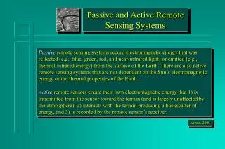
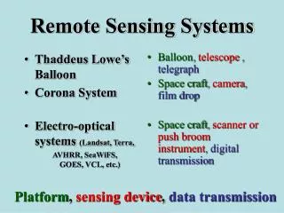
Multi-Spectral Remote Sensing Systems and Design Lecture 4 . Summer Session 21 July 2011. Radiometers and Spectrometers. Radiometer – An instrument that measures radiance in a specified wavelength region

Multi-Spectral Remote Sensing Systems and Design Lecture 4
E N D
Presentation Transcript
Multi-Spectral Remote SensingSystems and Design Lecture 4 Summer Session21 July 2011
Radiometers and Spectrometers • Radiometer – An instrument that measures radiance in a specified wavelength region • Spectroradiometer or spectrometer – An instrument that measures radiance continuously across a region of the EM spectrum or in multiple-bands across a region of the EM spectrum
Questions to ask when designing a multi-channel spaceborne radiometer • What reflectance characteristics are you trying to measure? Spectral resolution • How precisely do you have to measure these characteristics? Radiometric resolution • How large are the features of interest? Spatial resolution • What is the size of the patch being detected by the satellite? • How frequently and when do you have to measure the features of interest? Temporal resolution • How much data are being recorded by the radiometer and how do we retrieve these data? • How do variations in surface and atmospheric conditions affect the data quality?
Elements of a Remote Sensing System 4. Data Recorder 3. Sensing Device 5. Information Production System 6. Information Delivery System 2. Area or scene of interest 1. Information User
Instantaneous Field of View- IFOV • All radiometers have an instantaneous field of view • i.e. the angular dimension over which radiation is detected • Essentially, the footprint that a satellite is detecting at any one instant. • It’s circular.
Sensor IFOV (in degrees, ) H r Radius of circle within IFOV, r = H tan (/2) For very small IFOV, e.g., <<< 0.01º, r = H /2, where is in radians
Controls on Frequency of Coverage by a Satellite • The orbital time of the satellite • The width of the area being imaged by a satellite when it passes over the earth
Types of satellites (by orbit) • Polar orbiting • Geo-stationary
A satellite in low earth orbit (~800 km) takes about 90 minutes to complete a single circling of the planet (16 orbits/day) inclination Inclination: how far off of the poles they circulate - Many satellites have 99oinclination Earth Circumference = 39,350 km 39,350/16 = 2460 km Why is it designed to cross the equator early in the morning? - solar illumination - cloud cover
Satellite What would the viewing angle have to be in order to image the entire earth daily?? H = 800 km Swath width = 2460 km
Tan() = 0.5*width height Tan() = (0.5*2460)/800 Tan() = 1.65 = arctan(1.65) = 57 degrees H = 800 km Swath width = 2460 km
Satellite Viewing angle of 57° off nadir to image swath H = 800 km Swath width = 2460 km
Satellite How long to cover the Earth with this system? Viewing angle of 6.1° off nadir to image swath 16 orbits/day * 172 km = 2752 km/day imaged (width) H = 800 km Earth’s circumference = 39,350 km 39, 350/2752 = 14.3 days Swath width = 172 km
So, why doesn’t every imaging system have a wide swath and high resolution?? • There are trade-off’s! • Data volume storage limits • Perceived vs. actual footprint • BRDF • Atmospheric effects
Wide Swath / Low Resolution Narrow Swath/ High Resolution Image Size 2460 by 2460 km 172 by 172 km Ground area size (resolution or pixel size) 1 by 1 km 0.05 by 0.05 km (50 by 50 m) Number of radiometer channels 4 4 Images per orbit 16 228.8 Pixels per image per channel 6 million 11.8 million Pixels per orbit per channel 96 million 2.7 billion Pixels per orbit for all channels 384 million 10.8 billion If a sensor were to be both high resolution AND wide swath: Pixels per orbit for 4 channels: 155 billion Daily Pixels for Earth: 2.5 trillion Monthly Pixels for Earth: 743 trillion
Transferring data to the ground • Transmit the information directly to the receiving station as the satellite passes over the site • On-board recorder – record data, and then transmit to a ground receiving station • Use a satellite relay system to transmit data to a receiving station • TDRSS Tracking and Data Relay Satellite System Data volume is a major consideration in developing satellites radiometer systems
Problems with imaging over wide swaths • The size of your (perceived) ground footprint gets bigger as the angle off nadir gets large • Atmospheric effects increase • The bidirectional reflectance at the surface often changes • The emittance from the surface for the same surface cover type changes
Maximum look off-Nadir most scientists use Still usable, but starting to be un representative Relatively 1:1
Atmospheric effects • Effects of atmosphere on incoming/outgoing EM energy is proportional to distance traveled through the atmosphere • As incidence angle increases, atmospheric effects (scattering, absorption, attenuation) increase • Using wide swath width increases the requirements for precise atmospheric adjustmentof the data
Further information on this slide can be viewed at http://snrs.unl.edu/agmet/908/brdf_definition.htm
Narrow-Swath, Higher Resolution Wide-Swath, Lower Resolution -Coverage only every 15 to 20 days (less if cloud cover exists) +Daily coverage of area +High resolution imagery -Low resolution imagery -Higher data volumes requires on-board recording or direct transmission +Lower data volumes result in less stringent recording/direct transmission requirements +Narrow viewing angle results in lower atmospheric / bi-directional scattering effects, and consistent across-swath resolution -Wider viewing angle results in greater atmospheric / bi-directional scattering effects, and variable across-swath resolution Summary of System Tradeoffs Temporal resolution Spatial resolution Data volume Atmospheric effects
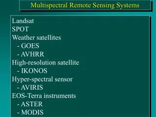
Categories of satellite radiometers • Wide swath, low resolution • 1000-2600 km swath, 500 to 1100 m • Moderate swath, moderate resolution • 100 to 200 km swath, 10 to 50 m resolution • Narrow swath, fine resolution • 5 to 15 km swath, 1 to 4 m resolution
Digitization of signals Recording device Radiance is detected by the sensor and converted to a number based on the intensity of the signal by an analog to digital converter Different sensors have different levels of sensitivity, which depends on radiometric resolution and determines: - Minimum and maximum signature levels - Number of divisions signal is divided into - e.g. Landsat = 8-bit radiometric resolution 0-255 (28)
The Pixel • A two-dimensional picture element that is the smallest non-divisible element of a digital image
Key components of a pixel • Size of the pixel on the ground - spatial resolution • Number of gray levels (brightness values aka digital numbers) recorded by a pixel - radiometric resolution
8 bits = 28 = 256 levels 10 bits = 210 = 1024 levels 16 bits = 216 = 65536 levels
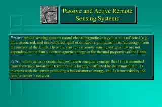
Types of Scanning systems • Multispectral scanners – scanning systems that detect and record reflected, emitted or backscattered energy from an area of interest in multiple, broad bands of the electromagnetic spectrum • Hyperspectral scanners – scanning systems identical to multispectral scanners, except they detect and record energy from hundreds of narrow bands of the electromagnetic spectrum
First Spaceborne MSS SatelliteEarth Resources Technology Satellite – ERTS-1 (Changed later to Landsat 1) • Launched 23 July 1972 • Contained two systems • 3 Channel Return Beam Vidicom (RBV) (channels 1 to 3) • 4 Channel Multispectral Scanner (channels 4 to 7)
ERTS-1 RBV System Return Beam Vidicon cameras Essentially 3 TV cameras operating in separate channels • 0.48-0.57 µm (green) • 0.58-0.68 µm (red) • 0.69-0.83 µm (near IR)
Landsat 1 MSS Channels or bands Band 4 is 0.5 to 0.6 um (green) Band 5 is 0.6 to 0.7 um (red) Band 6 is 0.7 to 0.8 um (near IR) Band 7 is 0.8 to 1.1 um (near IR)
Key Features of a Spaceborne MSS System • Detectors in the wavelength bands of operation • Optics to provide a fine instantaneous field of view to define the pixel size • Method to scan the earth’s surface • Data recording system • Data transmission system
Design Considerations in Land Surface MSS Systems • Number of bands sufficient to discriminate key land surface features • Trade-offs between swath width, pixel size, and frequency of coverage • Coarse resolution, wide swath, high frequency • Fine resolution, narrow swath, low frequency • Recording and down-loading data
Landsat • The first Landsat satellite was launched in July 1972 (what we just went over) • Initially called Earth Resources Technology Satellite (ERTS) and renamed Landsat at a later date • The Landsat MSS system evolved into the Thematic Mapper (TM) in 1982 • Thematic Mapper evolved into Enhanced Thematic Mapper (ETM+) in 1999 • Next: Landsat 8 – Landsat Data Continuity Mission…Operational Land Imager (OLI) • December 2011 (cross your fingers)