Development of a Read-Out Chip for Si-W Calorimeter: KPiX Overview
SLAC, Oregon, and BNL are collaboratively developing a read-out chip (ROC) called KPiX for the Si-W calorimeter, featuring 1024 pixels per ROC. The design is integrated into the structural framework and utilizes bump bonding to connect to detectors. Our architecture supports a similar strategy for silicon strips and can adapt for systems like HCal and muon detection. Key requirements include signal noise under 2000 e- and an efficient power consumption of less than 40 mW per wafer. This detailed report encompasses the technical specifications, signal processing methodology, and implications for various particle detection systems.

Development of a Read-Out Chip for Si-W Calorimeter: KPiX Overview
E N D
Presentation Transcript
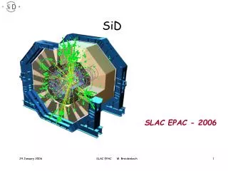
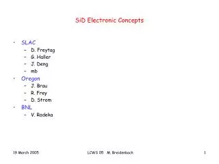
SiD Electronic Concepts • SLAC • D. Freytag • G. Haller • J. Deng • mb • Oregon • J. Brau • R. Frey • D. Strom • BNL • V. Radeka LCWS 05 M. Breidenbach
Overview • SLAC/Oregon/BNL is developing a read out chip (ROC) for the Si-W calorimeter. • Highly integrated into structural design – bump bonded to detector • 1024 pixels / ROC ---Thus working name KPiX • Rough concept for “DAQ” strategy. • Similar architecture with reduced dynamic range should work for Si strips. 2048 pixels / ROC • Similar architecture should work for HCal and muon system. • Will not work for very forward systems. LCWS 05 M. Breidenbach
Concept LCWS 05 M. Breidenbach
Electronics requirements • Signals • <2000 e noise • Require MIPs with S/N > 7 • Max. signal 2500 MIPs (5mm pixels) • Capacitance • Pixels: 5.7 pF • Traces: ~0.8 pF per pixel crossing • Crosstalk: 0.8 pF/Gain x Cin < 1% • Resistance • 300 ohm max • Power • < 40 mW/wafer power cycling (An important LC feature!) • Provide fully digitized outputs of charge and time on one ASIC for every wafer. LCWS 05 M. Breidenbach
Wafer and readout chip LCWS 05 M. Breidenbach
Detector Layout Real Thing LCWS 05 M. Breidenbach
Conceptual Design of W-SI Front-End ASIC Version 1.3 There is an 18 page technical document, now in its 4th major revision for register assignments, etc for the cold bunch structure. LCWS 05 M. Breidenbach
Cal strobe gated by 1024 long SR. Pixel pattern arbitrary. LCWS 05 M. Breidenbach
Event discriminator implemented as limiter followed by discriminator. Limiter holds off resets, permitting longer integration time for discriminator and data hold. Discriminator threshold selected from either of two ROC wide DAC’s. LCWS 05 M. Breidenbach
Pulse “Shaping” • Take full advantage of synchronous bunch structure: • Reset (clamp) feedback cap before bunch arrival. This is equivalent to double correlated sampling, except that the “before” measurement is forced to zero. This takes out low frequency noise and any integrated excursions of the amplifier. • Integration time constant will be 0.5 – 1 μsec. Sample synchronously at 2 – 3 integration time constants. • Time from reset 1 – 3 μsec, which is equivalent to a 1 – 3 μsec differentiation. • Noise: ~1000 e- for ~ 20 pF. (100 μA through input FET). LCWS 05 M. Breidenbach
Power LCWS 05 M. Breidenbach
Data Flow - ~ 4 Mb/train from backgrounds… LCWS 05 M. Breidenbach
Comments • The basic architecture should work with all the low occupancy sub-systems. • Including Tracker, EmCal, HCal, and muon system. • It does not address VXD issues – presumably CMOS to be developed – or the completely occupied Very Forward Calorimeters. • A variant might work in the forward regions of the tracker and calorimeters. • The architecture is insensitive to the bunch separation within a train. • The cost of a mask set is high, so development will be with (probably) 8 x 8 subsets instead of the 32 x 32 array. • The unit cost of a large number of chips seems fine - <~ $40. • Substantial design and simulation is done on EMCal Readout chip. Layout is progressing. • ~No work done on anything else. LCWS 05 M. Breidenbach