Logical Controllers Programming: Data Memorization, Timers, and Counters Overview
This guide explores advanced programming concepts for logical controllers focusing on data memorization, timers, and counters. It covers the key components, including setting and resetting functions based on logical conditions, pulse generation, and timer operations. Detailed ladder diagrams illustrate how to implement these concepts effectively, ensuring a clear understanding of how bits manipulate outputs and manage state transitions. Real-world examples demonstrate the practical application of these programming techniques in automation systems.

Logical Controllers Programming: Data Memorization, Timers, and Counters Overview
E N D
Presentation Transcript
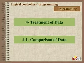
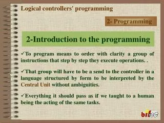
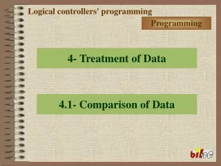
3-Other instructions Logical controllers' programming 3.1- Memorization of data Programming
SET Logical controllers' programming When the logical condition (000.00) that precedes the function SET it passes ON, the manipulated bit (physical exit 10.00) or (internal relay 200.00) it also passes ON and it stays in this state. 3.1- Memorization of data Ladder Diagram Statement List
RESET Logical controllers' programming When the logical condition (000.00) that precedes the function RESET it passes ON, the manipulated bit (physical exit 10.00) or (internal relay 200.00) it passes OFF and it stays in this state. 3.1- Memorization of data Ladder Diagram Statement List
3.2- Generation of pulses Logical controllers' programming DIF.UP -DIFU- When the state of the bit “000.01” raisin of OFFON the bit “1.00” it assumes the state ON, during a cycle of the Program.
DIF.DOWN -DIFD- Logical controllers' programming When the state of the bit “000.01” raisin of ONOFF the bit “1.00” it assumes the state ON, during a cycle of the Program 3.2- Generation of pulses
3.3- Timers Logical controllers' programming For the analysis made to the temporary diagram, we can end that for the contact him associated to the timer TIM it closes (ON), it is necessary that the condition sign (000.01) it stays shut (ON) during the time in that this to count.
TIM Logical controllers' programming Base of Time–000,0 999,9 (tenth of second) 1 second = 10 10 seconds = 100 1 minute = 600 Ladder Diagram 3.3- Timers Statement List
TIMH Logical controllers' programming Base of Time–00,00 99,99 (hundredth of second) 1 second = 100 10 seconds = 1000 1 minute = 6000 Ladder Diagram 3.3- Timers Statement List
Example of Programa TIM Logical controllers' programming Ladder Diagram Statement List 3.3- Timers
3.4- Counters Logical controllers' programming The counters count down, that is, for each pulse (OFF-ON) in bit’000.00 ' the value #0005 is count down in an unit until reaching the minimum value 0000.
Logical controllers' programming Reached 0000 contact him associated to the counter it closes (ON). THE bit 000.01 to any height makes the counter reset returning everything to the initial position. 3.4- Counters
3.4- Counters CNT Logical controllers' programming 000.00–Pulse for count down 000.01–Reset of the counter Ladder Diagram Statement List
3.4- Counters CNTR – Reversible counter Logical controllers' programming 000.00–Pulse for count up 000.01–Pulse for count down 000.02–Reset of the counter Ladder Diagram Statement List LD 000.00 LD 000.01 LD 000.02 CNTR 012 #0005
3.4- Counters Example of Programa CNT Logical controllers' programming Ladder Diagram Statement List