AGILENT 7500
AGILENT 7500. 1. Inductively Coupled Plasma Mass Spectrometry (ICPMS). Fundamental aspects of ICPMS Briefly, in this technique, singly charged analyte ions generated in an ICP are extracted into and measured with a mass analyzer.

AGILENT 7500
E N D
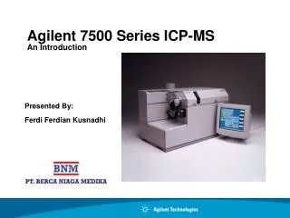
Presentation Transcript
AGILENT 7500 1.
Inductively Coupled Plasma Mass Spectrometry (ICPMS) • Fundamental aspects of ICPMS • Briefly, in this technique, singly charged analyte ions generated in an ICP are extracted into and measured with a mass analyzer. • The rapid development of ICPMS has been fueled by its unique measurement capabilities • Detection Limit: 1 to 100 ng/Lin many cases, these limits are 100 to 1000 times superior to those that can be routinely achieved by ICP-AES. • Spectral interferences • Isotopic ratio measurement capability 1.
ICP as an ion source When a system is in thermal equilibrium, the degree of ionization of an atom is given by the Saha equation (Note that the degree of excitation of an atom is described by Boltzmann equation: nine/na = 2Zi/Za(2πmkT/h2)3/2exp(-Ei/kT) where ni, ne and na are the number densities of the ions, free electrons and atoms in the plasma, respectively. Zi and Za are the ionic and atomic partition functions, respectively. m is the electron mass. k is the Boltzmann constant. T is the temperature. h is the Planck’s constant. Ei is the first ionization energy.
Degree of ionization is dependent on: • electron number density • temperature • ionization energy Assume: electron number density for an argon ICP: 4 x 1015 cm-3 ionization temperature: 8730 K Then the degree of ionization as a function of first ionization energy, predicted by the Saha equation.
From Jarvis et al., 1997 Over 80% ionized for elements having 1st ionization energies of less than 9 eV. The most poorly ionized elements: He, Ne, F, O, and N (<1%); Kr and Cl (1 – 10%) C, Br, Xe and S (10 –30%), P, I, Hg, As, Au and Pt (30 –80 %). Note that this calculation is carried out based on assumption of a local thermodynamic equilibrium (LTE) be reached.
1. Jarvis et al., 1997
1. Jarvis et al., 1997
Distribution of ions in the plasma From Houk ICP Course YO, Y(I), Y(II) EMISSION ZONES COURTESY VARIAN
Cooler central 1. Hotter area Jarvis et al., 1997
1. The optimized location of the orifice is determined by the elements of interest and other plasma conditions. Ionization needs time! Jarvis et al., 1997
1. The optimized location of the orifice is determined by the elements of interest and other plasma conditions. Ionization needs time! Jarvis et al., 1997
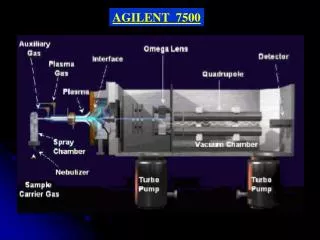
1.3 Ion sampling ICP/AES vis ICP/MS 1.3.1 Ion sampling interface
Interaction between plasma and sampling cone: • Intermediate temperature zone between plasma and cone (oxide formation) in this boundary layer (red color). • Plasma potential (sheath electrical by the interaction between the plasma and the conducting sampler) Boundary layer and sheath Boundary vs. Sheath region
Mach disk Supersonic jet Barrel shock
From Houk ICP Course 1.3.3 Supersonic jet The barrel shock and Mach are caused by collisions between fast atoms/ions from jet and the back ground gas, which reheat the atoms/ions and induce emission. To avoid losses of ions due to collisions and scattering, position the skimmer with its open tip inside the Mach disc.
A skimmer-sampler separation of 2/3 of the distance to the onset of the Mach disc usually Provides optimum ion transmission Sampler Mach disk Skimmer The position of the onset of the Mach disc is given by Xm = 0.67 D0(P0/P1)1/2 Xm = position of Mach dsic from the sampling orifice along the central axis D0 = diameter of the samplingorifice P0 = pressure of ICP P1 = back ground gas pressure in extraction chamber
Ion focusing • Serves to focus ions from the skimmer into the mass filter (analyzer) • Rejects neutral atoms • Minimize the passage of any photons from ICP (Electron Multiplier is photo/neutral sensitive) 10-2 Torr 10-5 Torr Omega (eliminate photons &neutrals) Einzel (Focus ion beam) Extraction (Extract ions from Plasma)
Space charge effects • Space charge effects are a consequence of the mutual repulsion between particles of like charge. • It is a consequence of Coulomb’s law, which quantifies the force (F) between two point charges (q and q’) separated by a distance r as F = k(qq’/r2) where k is a proportionality constant that depends upon the unit chosen for the other variables in the equation.
Interferences in ICPMS Mass spectral interferences Skoog et al., 1999, Instrumental Analysis
Isobaric overlap Isobaric interferences are due to two elements that have isotopes having substantially the same mass. Quadrupole instruments: differ in mass by less one unit.
Generally • Most elements in the periodic table have one (e.g. 59Co), two (e.g. Sm, Samarium), or even three (e.g. Sn) isotopes that are free from isobaric overlap. • An isobaric interference occurs with the most abundant (sad!) and thus the most sensitive isotope, e.g. the very large peak for 40Ar+ overlaps the peak for the most abundant calcium isotope 40Ca+ (97%) making it is necessary to use the second most abundant isotope 44Ca+ (2.1%). • Isotopes with odd masses are free from overlap, while with even masses are not. • No isobaric peak interferences below 36 m/z. Isobaric overlaps are exactly predictable!
Polyatomic Polyatomic ion interferences result from interactions between species in the plasma and species in matrix or atmosphere. Argon, hydrogen and oxygen are the dominant species present in the plasma and these may combine with each other or • With elements from the analyte matrix or • The major elements present in the solvents or acid used during sample preparation (e.g. N, S. and Cl)
?? 3000000 Vandercasteele and Block 1997
Vandercasteele and Block 1997 This type of interference is found largely at m/z values of below 82.
Jarvis et al., 1997 Polyatomic ion peaks in both H2O2 and HNO3 are identical to those identified in de-ionized water and these media are therefore considered ideal matrices. However, the spectra in an HCl or H2SO4 matrix are more complex.
Corrected for using a blanks • Estimate the response of the interference relative to the analyte • Reduce water entering Plasma
Refractory oxide ions Refractory oxide ions occur either as a result of incomplete dissociation of the sample matrix or from recombination in the plasma tail. • 16 (MO+), 32 (MO2+) or 48 (MO3+) mass units above the M+ peak • The relative level of oxides can be predicted from the monoxide bond strength of the element concerned. Those elements with the highest oxide bond strength usually give the greatest yield of MO+ ions. • Plasma operating conditions can dramatically influence the formation of oxide ions
Doubly charged ions • The formation of doubly charged ion in the plasma is controlled by the second ionization energy of the element and the condition of plasma equilibrium. • Only those elements with a second ionization energy lower than the first ionization energy of Ar will undergo any significant degree of 2+ formation. • The effect of 2+ ions is two-fold: • Sensitivity for the singly charged species • Spectrum interferences for others
Interference equations Isobaric interferences can usually corrected for by the use of elemental interference equations.
Arsenic determination in a Cl matrix: ArCl polyatomic ions formed, one of which has the same m/z as As (75). Cl: 35 (75.77%), 37 (24.23%) As a result, quantitative analysis of arsenic can have an error due to ArCl.
ArCl is present at m/z 75 and m/z 77 in the proportion to the isotope ratio of 35Cl : 37Cl, 75.77% : 24.23%, can be used to correct for the interference at m/z 75. • The ArCl counts at m/z 75 are calculated based on the m/z 77 ArCl count. By subtracting ArCl from the count at m/z 75, the correct As concentration can be obtained. As (75) = M (75) – (75.77/24.23) x ArCl (77) = M (75) – 3.132 x ArCl (77) [1] Where M (75) is the count number measured at m/z 75, As (75) is the count number contributed only by arsenic at m/z 75, and ArCl (77) is the count number contributed by polyatomic ion ArCl at m/z 77.
However, as selenium has an isotope at m/z 77, Se: 74 (0.89%), 76 (9.36%), 77 (7.63%), 78 (23.78%), 80 (49.61%), 82 (8.73%). By measuring the Se at m/z 82, the Se count at m/z 77 can be estimated, and subtracted from the counts at m/z 77 to calculate the counts due to ArCl. ArCl (77) = M (77) – (7.63/8.73) x Se (82) = M (77) – 0.874 x Se (82) [2] Where M (77) is the count number measured at m/z 77 and Se (82) is the count contributed by selenium at m/z 82.
Then equation 2 can be applied to equation 1: As (75) = M (75) – 3.132 x [M (77) – 0.874 x Se (82)] = M (75) – 3.132 x M (77) + 2.736 x Se (82) [3] So far, we have only considered ArCl and Se. What else? Kr interference at m/z 82! Kr: 78 (0.35%), 80 (2.25%), 82 (11.6%), 83 (11.5%), 84 (57.0%), and 86 (17.3%).
In some cases, Kr is found in the Argon gas supply (mainly from bottle Ar), therefore the signal at m/z 82 should be corrected: Se (82) = M (82) – (11.6/11.5) x Kr (83) = M (82) – 1.009 x Kr (83) [4] If this equation is applied to the equation 3: AS (75) = M (75) – 3.132 x M (77) + 2.736 x [M (82) – 1.009 x Kr (83)] = M (75) – 3.132 x M (77) + 2.736 x M (82) – 2.760 x Kr (83)
Matrix effects Observation and mechanisms • High dissolved solids • blockage of the entrance aperture of the sampling cone • The deposition of salts leads to a decrease in the aperture diameter, so that the sensitivity worsens and the signals gradually decrease as a function of time.
Suppression and enhancement effects • Ionization suppression: M = M+ + e- Introduction of an easily ionized element contributes strongly to the electron density in the plasma and therefore shifts the ionization equilibrium so that the analyte elements are ionized to a lesser extent. • Space charge effects: Lighter analyte ions can be expected to suffer more from this effect than heavier ones, and are thus preferentially lost from the transmitted ion beam.
Methods to correct for or overcome matrix effects • Dilution • Easy • Detection limits sacrificed • Matrix matching Of course, when the analyzed matrix is also added to the standards, correction for matrix effects is possible. This method can only be applicable for simple matrices, e.g. metals, but is clearly not applicable for complex matrices of varying composition.
Use of internal standards • Allows correction for random fluctuations of the signal • Allows correction for systematic variations of the analytical signal in samples and standards due to matrix effects • The signal for the internal standard element should be influenced in the same way as that for the analyte • Choose the internal standard with a mass number as close as possible to that of the analyte
Standard addition • A safe method for samples of unknown composition and thus unknown matrix effect. • Time consuming • Chemical separation • Allow pre-concentration of the analyte elements • Avoidance of spectral interference. • Isotope dilution
Cool Plasma • The first breakthrough to reduce some of the severe polyatomic overlaps • Use low temperature plasma to minimize the Ar and matrix-based polyatomic species that form under normal plasma conditions (1-1.4 KW rf power) • Cool plasma uses 500-800 KW rf power
Unfortunately cool plasma: • Useful only for a small number of elements • Element that form strong bond with O2 and F cannot be decomposed because of the low plasma energy. • Elements with high ionization potential cannot be ionized.
Hexapoles • Collision Reaction Cell