Download
1 / 35
380 likes | 541 Vues
Learn how geometric design influences highway safety and efficiency, considering factors like speed, traffic volume, topography, and driver characteristics. Design elements such as curves, lane width, and vertical alignment play a critical role. Understand the importance of setting appropriate standards to ensure smooth traffic flow and minimize accidents.

E N D
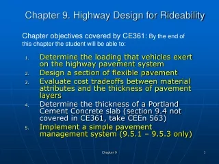
Geometric Design of Highway FacilitiesChapter 16 Dr. TALEB M. AL-ROUSAN
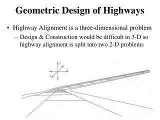
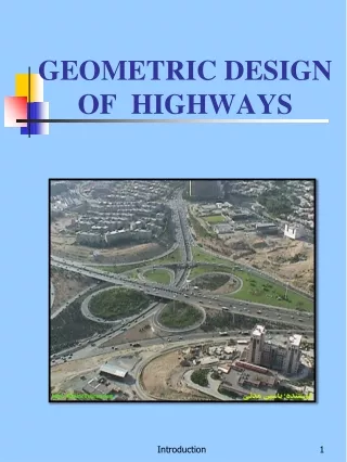
Introduction • Geometric design of highway facilities deals with the proportioning of the physical elements of highways such as vertical & horizontal curves, lane width, cross sections, and parking bays. • The characteristics of the driver, pedestrian, vehicle, and road serve as the basis for determining the physical dimensions of these elements. • Example: length of vertical curve or radii of circular curve are determined such that the minimum stopping sight distance is provided on the curve for the design speed of the highway. • Basis objective in geometric design of highways is to produce smooth-flowing, crash-free facility • These objectives can be achieved by having a consistent design standards along the highway that satisfy the characteristics of the driver and vehicle,
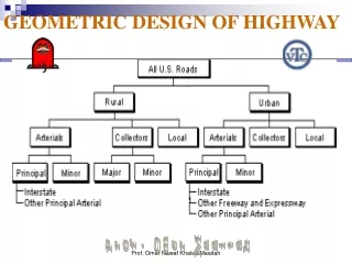
Factors Influencing Highway Design • Highway functional classification. • Expected traffic volume and traffic mix. • Design speed. • Topography of the area. • Level of service to be provided. • Available funds. • Safety. • Social and environmental factors.
Factors Influencing Highway Design • These factors are often interrelated: for example: • design speed depends on functional classification which in turn depends on expected traffic volume. • Design speed depend on topography specially when limited funds are available. • Principal factors in highway design are: • LOS • Traffic volume • Design speed • Design vehicle • These factors couple with mode characteristics to determine standards for the geometric characteristics of the highway (cross section and horizontal and vertical alignment) • For example: appropriate geometric standards should be selected to maintain a desired level of service for known proprtion of different types of vehicles.
Highway Design Standards • Design hourly volume • Design speed • Design vehicle • Cross-section elements • Width of travel lane • Shoulders • Median and roadside barriers • Curbs and gutters • Guard rails • Sidewalks • Cross slopes • Side slopes • Right of way
Design Hourly Volume (DHV) • Is the projected hourly volume used for design. • Usually taken as percentage of the expected ADT on the highway. • Figure 16.3 relation between hourly volume and ADT on rural roads • The 30th highest hourly volume is usually selected as the DHV based on the characteristics of the curve in figure 16.3. • For rural highways it is usually between 12% and 18% of the ADT (15% as Avg.) • The 30th highest hourly volume should not be used for highways with unusual or high seasonal fluctuation in the traffic flow.( use 50% of the volume that occur for only few peak hours during the design year as the DHV).
Design Hourly Volume (DHV) • The 30th highest hourly volume can also be used as the DHV for urban highways • Determined by applying between 8% and 12% to the ADT. • Other relations for urban roads with seasonal fluctuation in traffic flow (use average of the highest afternoon peak hour volume for each week in the year as the DHV).
Speed and Design • Speed reduces the visual field, restricts the peripheral vision and limits time to receive and process information • Higher speeds must have better design features (i.e., freeways versus two-lane roads) (lower information processing demands) • May create problems: • Nighttime condition: headlights not far enough for a driver to stop safely (e.g., lower speed limits) • Driver fatigue caused by lack of visual stimulation
Design Speed • Is defined as the maximum safe speed that can be maintained over a specified section of highway when conditions are so favorable that the design features of the highway governs • Is a selected speed to determine the various geometric features of the roadway. • It depends on: • Functional classification of the highway. • Land use of the adjacent area. • Topography of the area: • Level terrain: flat, horizontal and vertical sight distances are long or can be achieved without much construction difficulties. • Rolling terrain: has natural slopes above & below the highway grade, with occasional steep slopes that restrict the normal vertical and horizontal alignment. • Mountainous terrain: has sudden changes in ground elevation in both longitudinal and transverse direction, requires excavation to achieve acceptable alignment.
Design Speed Cont. • Design speed selected should not be significantly different from the speed at which motorists will expect to drive. • The average trip length on the highway also should be considered in selecting the design speed (highways with longer trips should be designed for higher speeds). • Design speeds range from 20 mi/h to 70 mi/h with intermediate values at 10 mi/h. • Freeways (60-70 mi/h) • Arterial roads ( 30-60 mi/h). • Tables 16.1 and 16.2 give recommended values for min. design speeds for different classes of highways. • It is selected to achieve a desired level of operation and safety on the highway. • It is one of the first parameters selected in the design process because several other design variables are determined from it.
Design Speed Cont. • Design features influencing speed: • curvature, • superelevation • sight distance • It should fit the travel desires and habits of nearly all drivers • Drivers do not adjust their speeds to the importance of the highway, but to their perception of the physical limitations. • Running speed should be lower than design speed • It is desirable to use design speeds in increments of 5 mph • Posted speed should be set at the 85th percentile (speed limits should be in 10 mph increments)
SPEED • Operating Speed • Defined as the speed at which drivers are observed operating their vehicles during free-flow conditions • 85th percentile most commonly used measure of operating speed • Running Speed • The speed at which an individual travels over a highway section (measured as distance over time) • Use to measure level of service and road user costs • Usually computed at different locations on the segment (spot speed)
Design Vehicle • Is the vehicle selected to represent all vehicle on the highway. • Its weight, dimensions, and operating characteristics will be used to establish the geometric standards of the highway such as radii at intersections and turning roadways. • The design vehicle selected is the largest that is likely to use the highway with considerable frequency.
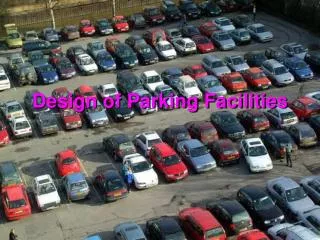
Design Vehicle Cont. • ٍِِAASHTO guidelines for selecting a design vehicle: • Passenger car : when a parking lot or a series of parking lots are the main traffic generators. • Single-unit truck: for the design of intersections at local streets and park roads (Urban intersections) • City transit bus: at intersections of state highways and city streets that serve buses with relatively few large trucks. • Large school bus (40 ft long) or conventional bus (36 ft long): at intersections of highways and low volume county highways or township/local roads with less than 400 ADT. (rural intersections) • WB-20 or larger size : at intersection of freeway ramp terminals and arterial cross roads, and at intersections of state highways and industrialized streets that carry high volumes of traffic.
Cross-Section Elements • Principal elements: • Travel lanes • Shoulders • Medians (for some multi-lane highways). • Marginal elemnts • Median and roadside barriers • Curbs • Gutters • Guard rails • Side walks • Side slopes. • See Figures 16.4 & 16.5 for typical cross sections for two lane highways and multilane highway, respectively.
Width of Travel Lanes • Usually vary from 9 to 12 ft. • Most arterials have 12 ft travel lanes. • For two –lane, two-way Rural roads, 12 ft is recommended. • (10 -11 ft) may be used on two-lane, two-way rural roads but the following should be considered: • When pavement surfaces are less than 22 ft the crash rates for large trucks tend to increase. • Capacity of the highway significantly decreases. • Lane widths of 10 ft are used only on low-speed facilitiesز • Lane width of 9 ft are used occasionally when traffic volume is low and there are extreme right-of-way constraints.
Shoulders • Is contiguous with the traveled lane. • Provide area for vehicle to: • Emergency stops • Accommodate bicycles • Laterally support pavement structure. • Shoulder width is known as: • Graded: the whole width of the shoulder. • Usable: part of graded shoulder that accommodate parked vehicle. • usable = graded when side slope is 4:1 or flatter (H:V). • It is essentials that shoulder be: • flush with the edge of the traveled lane • sloped to facilitate drainage (2 - 6%) • More notes: increase sight distance on horizontal curves, increase highway capacity if used by vehicles in emergency cases, its surface is preferred to be rougher than travel lanes.
ShouldersCont. • AASHTO recommends shoulder width of (10 -12 ft) for highways having large number of trucks and on highways with high traffic volumes and high speeds. • Min. shoulder width of 2 ft may be used on the lowest type of highways (when terrain is difficult and volumes are low). • When pedestrians and bicycles ate permitted to use the shoulder , the min width should be (4 ft) • Preferably shoulder width (6- 8 ft). • For divided arterials with two lanes in each direction, Usable median shoulder min. width can be (3 ft) since rarely used for stopping. • For divided arterials with three or more lanes in each direction, Usable median shoulder min. width can be (8 ft) since drivers in difficulty on the lane next to the median often find it difficult to maneuver to the outside shoulder.
Medians • Is the section of a divided highway that separates the lanes in opposing directions. • Width of median is the distance between the edges of the inside lanes, including the median shoulders. • Median functions: • Provide recovery area for out-of-control vehicles. • Separating opposing traffic. • Providing stopping areas during emergencies. • Providing storage areas for left-turning and U-turning vehicles. • Providing refuge for pedestrians. • Reducing the effect of headlight glare. • Providing temporary lanes and cross-overs during maintenance operations.
Medians Types • Can either be: • Raised • Flush • Depressed 1- Raised Medians • used in urban arterial streets as they facilitate the control of left turning traffic at intersections by using part of the median width for left-turn only lanes. • Disadvantages: • possible loss of control of the vehicle if the median is accidentally struck. • casting of shadow from oncoming headlights which results in drivers having difficulty seeing the curb
Medians Types Cont. 2- Flush Medians • Commonly used on urban arterials • Can be used on free-ways but with a median barrier. • Should be crowned to facilitate drainage of surface water. • The practice of in urban areas to convert flush medians into two-way left-turn lanes is popular as it increases the capacity of the highway. 3- Depressed medians • Used on freeways. • More effective in draining surface water. • Side slopes of 6:1 and 4:1 can be adequate.
Medians Width • Vary from (4 - 80 ft) or more. • The wider the median, the more effective it is in providing safe operating conditions. • For 4-lane urban freeways (min of 10 ft = 2 (4 ft shoulders) + (2 ft median barriers)). • For 6-lane urban freeways (min of 22- 26 ft). • For urban collector streets ( 2- 40 ft) depending on the median treatment. • For paint-strip separation medians (2- 4 ft). • For narrow raised or curbed areas (2-6 ft). • For Curbed sections (16-40 ft) because it provides space for protecting vehicles crossing an intersection.
Median Barriers • Median barriers are longitudinal system used to prevent an errant vehicle from crossing the portion of a divided highway separating the traveled ways for traffic in opposing directions. • Used to protect vehicles from obstacles or slopes on the roadside • Used to shield pedestrians and property from the traffic stream. • provision of the median barrier must be considered when: • Traffic volumes are high. • Access to multi-lane highways and other highways is only partially controlled. • Physical characteristics of the median of a divided highway may create unsafe conditions such as (sudden lateral drop-off or obstacles. • See Figure 16.7 for typical median barriers
Median and Roadside Barriers • Roadside barriers are provided whenever conditions exist on the side of the road that warrant protection of vehicles. • When slope of embankment is high • When there is a roadside object such as a view of an overhead bridge. • See Figure 16.6 for typical roadside barriers. • Details available in: AASHTO Roadside Design Guide
Curbs and Gutters • Curbs: Raised structures made of either Portland cement concrete or bituminous concrete (rolled asphalt curb) that are used mainly on urban highways to : • Delineate pavement edges and pedestrian walkways. • Control drainage. • Improve aesthetics. • Reduce right-of-way. • Classes: vertical & Sloping
Curbs Classes • Vertical Curbs: • 6-8 inch high with steep sides, designed to prevent vehicles from leaving the highway. • Should not be used in conjunction with traffic barriers, because they could contribute to vehicle rolling over the traffic barriers. • Should not be used on highways with design speeds (> 40 mi/h) because at such speeds it difficult for the driver to retain control of the vehicle after an impact with the curb. • Sloping Curbs: designed so that vehicles can cross them if necessary • See Figure 16.8 for typical highway curbs.
Gutters • Gutters or also known as drainage ditches. • Usually located on the pavement side of curbs to provide the pricipal drainage facility of the highway. • They are sloped to prevent any hazard to traffic (5- 8 % cross slopes) • (1- 6 ft) wide. • Can be designed as V-type sections or as broad, flat, rounded sections.
Guard rails • Are longitudinal barriers. • placed on: • the outside of sharp curves. • Sections with high fills (embankments > 8 ft) • Shoulder slopes > 4:1. • Main Function: prevent vehicles from leaving the roadbed. • Shapes commonly used: W beam and the box beam. • Weak post system: provides for the post to collapse on impact, with the rail deflecting and absorbing the energy due to impact.
Sidewalks • Usually provided on roads in urban areas. • Seldom provided in rural areas (in rural high-speed highways with high pedestrian concentrations (areas adjacent to schools, industrial plants, and local businesses). • Sidewalks are generally provided when pedestrian traffic is high along main or high-speed roads in either rural or urban areas. • Sidewalks are necessary on arterials with no shoulders even when pedestrian traffic is low. • Sidewalks should be provided along both sides of collector streets in urban areas to provide pedestrian access to schools, parks, shopping centers, and transit stops. • Sidewalk Min. clear width of (4 ft) in residential areas, and (4 – 8 ft) in commercial areas.
Cross Slopes • Pavements on straight sections of two-lane and multilane highways without medians are sloped from the middle downward to both sides of the highway. This provide a cross slope (crowned). • This type enhance the flow of surface water a way from the pavement. • The cross slopes on divided highways are provided by either : • crowning the pavement in each direction (mainly used in areas with heavy rain and snow) • Advantage: quick drain of surface water from traveled roadway during heavy rain storm. • Disadvantage: more drainage facilities are required such as inlets and underground drains. • Sloping the entire pavement in one direction. • See Figure 16.9 for both cross slopes arrangements.
Cross Slopes Cont. • Pavements in determining the rate of cross slope for design, two conflict factors should be considered: • Steep slopes are required for drainage. • But it is undesirable that vehicles will tend to drift to the edge of the pavement under icy conditions • (optimize drainage and safety issues). • Recommended cross slopes: • 1.5 – 2 % for high-type pavements. • 2 – 6% for low-type pavements.
Side Slopes • Side slopes are provided on embankments and fills to provide Stability for earthworks. • Also, serve as safety feature by providing a recovery area for out-of-control vehicle. • Important sections of the side slope: hinge point, fore slope, and toe of the slope. • Hinge point: • May cause vehicle to jump into the air while crossing it resulting in loss of control by the driver. • Rounding the hinge point will enhance control.
Side Slopes Cont. 2- Foreslope • Area that serves as a recovery area, where vehicle speed can be reduced and other recovery maneuvers can be taken to regain control of the vehicle. • Should be 3:1 or flatter (H:V) 3- Toe of the slope • Should be rounded in order to facilitate the safe movement of vehicles from the foreslope to the backslope. • See Figure 16.10 for desgnation of roadside region • See Table 16.3 for recommended values of foreslope and backslope
Right of Way (ROW) • Is the total land area acquired for the construction of the highway. • Its width should be enough to: • Accommodate all elements of the highway cross section. • Any planned widening of the highway. • Any public utility facilities that will be installed along the highway. • In some cases the side slopes may be located outside the ROW on easement areas. • (40 – 60 ft) for two-lane urban collectors • (min. of 84 ft) for two-lane arterials. • (64 – 108 ft) for undivided 4-lane arterials. • (120 – 300 ft) for divided arterials. • The min. width of ROW for freeway depend on the number of lanes and the existence of frontage roads.