Resolving Synchronisation Challenges in RF Linacs for FELs
120 likes | 161 Vues
Explore key issues and strategies in synchronising X-band linacs for Free Electron Lasers, focusing on timing stability, clock synchronization, phase errors, and RF path length requirements. Learn about components like klystrons, waveguides, and phase shifters.

Resolving Synchronisation Challenges in RF Linacs for FELs
E N D
Presentation Transcript
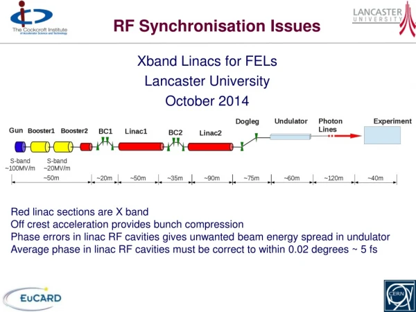
RF Synchronisation Issues Xband Linacs for FELs Lancaster University October 2014 Red linac sections are X band Off crest acceleration provides bunch compression Phase errors in linac RF cavities gives unwanted beam energy spread in undulator Average phase in linac RF cavities must be correct to within 0.02 degrees ~ 5 fs
LCLS Klystron SLAC achieving 0.08o stability translate to about 0.32o at XBand
Timing Problems • Stability • Oscillators shift period with temperature, vibration etc. • VCO shifts period with applied voltage • Atomic clock Df/f ~ 10-17 ~ 1 fs per minute • Synchronisation • Two clocks with different periods at same place (PLL) • Identical delivery time to two places (Crab Cavity Problem) • Same clock at two places • Resynchronisation requires constant propagation time of signal • Detector with femtosecond accuracy • Trigger an event at a later and a different location • Needs two stable clocks which are synchronised • Must be able to generate event from clock pulse with tiny jitter • 10 fs looks achievable see work at DESY and MIT
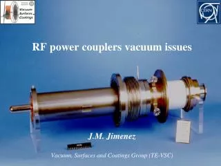
Clock to cavity LLRF control - feedforward to next pulse based on last pulse and environment measurements Optical clock signal Locked microwave oscillator Solid state amplifier IQ modulator Extremely sensitive to modulator voltage Solid state amplifier TWT amplifier Klystron Waveguide Every connector adds uncertainty Waveguide Pulse compressor sensitive to temperature Waveguide Cavity
CLIC Cavity Synchronisation CLIC bunches ~ 45 nm horizontal by 0.9 nm vertical size at IP. Cavity to Cavity Phase synchronisation requirement So need RF path lengths identical to better than c Dt = 1.3 microns
RF path length measurement RF path length is continuously measured and adjusted 4kW 5ms pulsed 11.8 GHz Klystron repetition 5kHz Cavity coupler 0dB or -40dB Cavity coupler 0dB or -40dB Waveguide path length phase and amplitude measurement and control Forward power main pulse 12 MW Single moded copper plated Invar waveguide losses over 40m ~ 3dB -30 dB coupler -30 dB coupler Expansion joint Expansion joint LLRF Magic Tee LLRF Reflected power main pulse ~ 600 W Reflected power main pulse ~ 500 W Phase shifter trombone Phase shifter trombone (High power joint has been tested at SLAC) Waveguide from high power Klystron to magic tee can be over moded Phase Shifter Main beam outward pick up Main beam outward pick up From oscillator 48MW 200ns pulsed 11.994 GHz Klystron repetition 50Hz Vector modulation 12 GHz Oscillator Control
Board Development Front end electronics to enable phase to be measure during the short pulses to an accuracy of 2 milli-degrees has been prototyped Digital phase detector Wilkinson splitter MCU PLL controller 10.7 GHz VCO Power Meter Output Input 1 DBMs Input 2 Power Meter Output
Phase measurement accuracy Accuracy depends on measurement bandwidth due to noise limitations (bandwidth determines minimum measurement time). Table below shows data for a single mixer + amplifier with 14 dBm power input: can use 4 to double accuracy and use more power. High Speed op amp Double balanced mixer Reflection from cavity 1 Variable LPF Voltage to oscilloscope /ADC Reflection from cavity 2
Results (from slide 7) 2.54mV/mdeg 2.17 mV/mdeg 2.17 mV/mdeg 7 kHz 200 kHz 30MHz To oscilloscope Coax line stretchers 12 GHz Source Coax lines Coax line Mixer Splitter March 2012
Waveguide choice Rectangular invar is the best choice as it offers much better temperature stability-> Expands 2.3 microns for 35 m of waveguide per 0.1 °C.
LLRF Hardware Requirements • Fast phase measurements during the pulse (~20 ns). • Full scale linear phase measurements to centre mixers and for calibration. • High accuracy differential phase measurements of RF path length difference (5 μs, 5 kHz). • DSP control of phase shifters. Linear Phase Detector Amp + LPF 10.7GHz Oscillator DBM DBM ADC Amp + LPF ADC DSP DBM DAC Wilkinson splitters -30 dB coupler -30 dB coupler To Cavity Magic Tee To Cavity Manual phase shifter for initial setup Fast piezoelectric phase shifter Prototype systems have been developed.