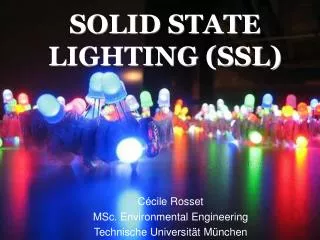
SOLID STATE LIGHTING (SSL)
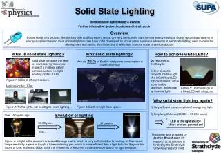
Explore the evolution of lighting technologies, focusing on Solid-State Lighting (SSL) with Light Emitting Diodes (LEDs), its mechanism, fabrication process, and color variations. Learn about the environmental benefits and energy efficiency of SSL. Reduced heat generation, longer lifespan, and lower energy consumption make SSL a sustainable alternative. Discover the science behind LED emission processes, bandgaps, and color temperatures. Witness the impact of SSL on reducing CO2 emissions and combating climate change through efficient lighting solutions.


SOLID STATE LIGHTING (SSL)
E N D
Presentation Transcript
SOLID STATE LIGHTING (SSL) Cécile Rosset MSc. Environmental Engineering Technische Universität München
1 Introduction • History of Lighting • 3 traditional Technologies: • Fire Incandescence • Fluorescence & High Intensity discharge Incandescent bulbs Fluorescent bulbs Oil lamp
1 Introduction • The fourth lighting technology SSL: Creation of first light emitting diodes (LED) • Solid: Light emitted by a solid: a piece of semiconductor At that time, LEDs were used for showing the time in an alarm clock or as a battery indicator
Lighting corresponds to 19% of the worldwide energy consumption. Reducing energy consumption by using LEDs will significantly reduce the level of CO2 emissions, therefore positively impacting climate change 1 Introduction • SSL: a new alternative to other lighting technologies? World Lighting Pollution • Reduced heat generation • Use of less power • Longer life span
2 LED Mechanism • Process of emitting Light • n-type & p-type semiconductors are combined in one device. • With the application of a voltage between the p-side and the n-side, free electrons from the n-type side go to the p-type side through the junction. • When an electron meets a hole, it recombines and thus releases its energy by emitting a photon.
Electrons injected Holes injected 2 LED Mechanism • Forward-biased pn junction
2 LED Mechanism • Direct / Indirect bandgap: • LEDs are made of direct bandgap semiconductors with bandgaps corresponding to near infrared, visible, or near ultraviolet light. The minimum of the conduction band lies directly above the maximum of the valence band. • Silicon has an indirect bandgap: For the recombinqtion of electrons and holes; the participation of a phonon (or a defect) is needed to conserve momentum
2 LED Mechanism • Light extraction • Snell’s law: • Light is unable to escape at angles greater than • defines the solid angle=projection on the surface area
2 LED Mechanism • Different geometries increasing the extraction of light
2 LED Mechanism • Wavelentgh and colour • The wavelentgh, and therefore the colour depends on the band gap of the semiconductor material. Red: GaAlAs Blue: InGaN UV: InGaAs
2 LED Mechanism Colours available: (Blue and white are much harder to obtain) • UV & blue LEDs For a long time unavailable; relied on blue coating! • The first blue LED was designed several years ago using SiC An ultraviolet GaN LED BUT: Poor efficiency! • 1993: Efficient GaN-based LEDs • Today: InGaN-based LEDs, intensity 5x bigger than with GaN
2 LED Mechanism • White LEDs • 1st technique: Found in 1993, when the first blue LED was produced. By juxtaposing at a certain distance blue, red, and green LEDs, white light was obtained. Most simple method but not often used nowadays. • 2nd technique: found in 1996 by Nichia Corp. and Fraunhofer Institut • Start with LED with an active layer made of InGaN • Cover this structure is covered with a yellow phosphor crystal coating (Ce3+:YAG). • The LED chip emits blue light, which is converted to yellow light by the phosphor. Phosphorescence Luminescence
GaN or InGaN LED 2 LED Mechanism • White LED Ce:YAG 3 kinds of white light, depending on the temperature: • 4000-4500 K, Incandescant or warmwhite • 5000-6500 K, Pure white • 7000-8000 K, Cool white
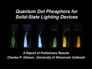
2 LED Mechanism • Other techniques of creating white LEDs • Coat near ultra-violet (NUV) with europium-based red and blue emitting phosphors • Transfer NUV radiation to visible light via the photoluminescence process in phosphor materials • Method less efficient then with the blue LED because of photodegradation of the epoxy resin used in LED packaging. 1. 2. • Coat blue LEDs with quantum dots, which absorb the blue light and emit a warm white light.
2 LED Mechanism • Color temperature and color mixing • An LED gives a pure monochromatic colour (on the edges of the CIE diagramm) • By mixing these colours a new one can be obtained. CIE diagram of human vision
3 LED Fabrication process • LED Growth • Growth of a thin layer of semiconductor (InGaN or AlGaInP, depending on the colour we want): • For AlGaInP, GaAs substrates are used (typ. diameter 150 mm) • For InGaN, SiC substrates (diameter 75 mm) or • Al2O3 substrates (diameter 50mm) • Further fabrication steps, comparable to silicon device fabrication
3 LED Fabrication process • Final structure of an GaN-LED: • electrical contacts to the p- and n-layers are both on the top surface of the device because of the insulating sapphire substrate. • the area of the contact to the p-layer has to be maximized to promote current spreading maximizes light emission and minimizes turn-on voltage and series resistance Because most of the light generated at the junction escapes the device through the top surface the large-area p-contact has to be made as transparent as possible outside the area where electrical bond wires are attached
Exemple: n-Butyllithium , C4H9Li 4 Towards a better efficiency • Fabrication process: MOCVD • MOCVD: metal-organic chemical vapor deposition • Chemical process used to grow quantum wells, thus to produce high purity, high performance solid materials • It’s a CVD process that uses metalorganic source gases • (chemical compound containing bonds between carbon and metal) • Reduction of dislocation density at the GaN epitaxial surface • Aim: To reduce the voltage at the operating current
4 Towards a better efficiency • Quantum efficiency • Quantum wells are potential wells that confine particles, which were originally free to move in three dimensions, to two dimensions, forcing them to occupy a planar region the internal QE of double heterostructure can be greater than 99% Double Heterostructure: change in bandgap
4 Towards a better efficiency • Lowering the operating temperature: Flip chip • Normal LED: • Big thermal resistance in thermal conduction path • Large amount of heat transferred from active layer through front face of LED and the encapsulating material and then dissipated into the air • Flip Chip LED: • designed with a thermal conductive submount and metal interconnections to conduct most of the heat through submount
4 Towards a better efficency • State-of-the-art The present state-of-the-art is 30% external efficiency in AlGaAs-based LEDs, employing a thick transparent semiconductor superstrate, and total substrate etching in a particularly low-loss optical design. Efficiency of 43% attained with an efficient NUV LED. The device structure consists of an MQW on a lateral epitaxy on a patterned surface and is flip-chip mounted on a silicon substrate. • Avantages of QDs (CdSe) over phosphor for white light generation Tunability of the final emission spectrum, by controlling the particle size distribution and/or surface chemistry thus white light colour is better quantum efficiency of 76% (in solution) for a blue emission, in GAN led
5 Different types of LEDs • Organic LED & Polymer LED These are LEDs whose emissive electroluminescent layer is composed of an organic compound or polymer that will luminesce blue, green and red, and are covered with a transluscent material. Advantages: -more easily integrated with other electronic components -it can emit white light intrinsically Problems: degradation in air & easily damaged by exposure to water
6 Limiting factors • Cost Competitiveness • Now, LED prices are 10 times higher than of incandescent light bulbs BUT: Better efficiency and longer lifetime • Narrow angle of emission • To use LEDs in ambient lighting, multiple LEDs are asembled in a single fixture. This leads to sharp shadows. • High quality variation • Inexpensive LEDs have inconsistent colour temperature and light output • Poor Quantum efficiency • LEDs are currently limited by poor internal quantum and light-extraction efficiency, but photonic crystals offer a potential solution to both problems.
7 Perspectives & Advantages • Good efficiency & durability • Associated with perfect material and devices, LEDs would require only 3 Watts to generate the light obtained with a 60-Watt incandescent bulb • LEDs can provide 50 000 hrs of life compared to 1000 hrs with incandescent light bulbs Figure 1. LED vs. conventional light sources degradation in light output over time
7 Perspectives & Advantages • Good stability • Due to their solid state, they can withstand vibrations better and have no filament that might break • They are capable of functioning in many environments (except OLEDs!) • An experiment made by ilight showed that a LED sign still worked after a blast of shotgun!
7 Perspectives & Advantages • Reduction of energy consumption • LEDs require less current than incandescent bulbs • Comparison with incandescent bulbs: When cold, an incandescent filament draws ten times as much current as it does during normal operation. The initial powering of hundreds of incandescent bulbs simultaneously causes significant voltage surges that lead to lamp failures.
7 Perspectives & Advantages • Reduction of heat emission • Less heat emission • Lens stays cooler • Less energy wasted • Some LED lamps are designed with series resistors to limit the operating current, resulting in no cold filament current variation. • Room temperature stays cooler, so we don’t need further air conditioning
7 Perspectives & Advantages • Allows wide variety of lighting • Artificial lighting similar to daylight • More control of the colour and intensity • SSL can be coupled to light pipes • Light can be efficiently and flexibly distributed • Interesting design possibilities: they can be placed on floors, walls, ceilings or furniture!
7 Perspectives & Advantages • White LED: The Future Lighting Technology • In the past 6 years: Tremendous gain in energy efficiency, brightness and lifespan • For now, between 25 & 50% efficiency, but some researchers think it’s possible to have 90% efficiency! Contrary to the traditional light bulb which has 5% efficiency and no perspective to do better! • Although they are still expensive, they could come in the market for residential lighting in the next 10 or 15 years
8 Applications • Common application: Digital clock, battery level indicator, torch • Traffic signals, street light • Buildings • Outdoor: runway in airports • Residential • Information boards
9 Challenges • Phosphor challenge • Better understanding of the physics of semiconductors used; AlGaInP and AlGaInN materials and nanostructures • For white light: Improved wavelength-conversion and colour-mixing technologies for generation of white light
10 Research and development going on • Projects sponsorised by the DOE: • The US Department of Energy promotes research on SSL by allocating $21 million to 13 projects! • Develop a polymer OLED using advanced polymer synthesis to allow large-scale manufacturing of p-OLED lamp • Understand & solve the problem of low radiative emissions in green LEDs • Create a GaN substrate with very few dislocations in order to improve blue LED efficiency • And many more…
10 Research and development going on • Project : “LED lights might light homes in less than 3 years” • University of Glasgow • Investigation of the possibility of making microscopic holes on the surface of the LED to extract more light, in order to increase the brighteness without increasing the energy consumption • Technique used: Nano-printing lithography, direct impression of the holes
11 Environment • Result doubly environment-friendly Incandescent traffic lights replaced by LEDs in USA: economy of 2.5 billion kWhours = US$ 200 million = 3 billion kilos of CO2 released in the atmosphere • Less current consumption • (less electricity burned) • Less heat produced • Less CO2 emissions • Less light pollution • Positive impact on global warming
12 Future & perspectives • Based on semiconductor material, like microprocessor • Important research and progress for these materials • In comparison with processors becoming faster and cheaper each year, we can expect the LED to become brighter, more energy efficient, have a higher longevity and become cheaper
13 Interesting websites • http://lighting.sandia.gov • http://www.loe.org • http://www.enn.com • http://www.netl.doe.gov • http://www.nichia.com • http://cree.com • www.lumileds.com
2 LED Mechanism • Semi-conductor diode Solid material that is between insulators and conductor: Behaves like an Insulator (large bandgap) at room temperature Behaveslike conductor (no bandgap) when applying electric field
2 LED Mechanism • Doping to enhance the conductivity • Addition of impurities in the lattice: • p-type: enhanced conductivity with valence electron-deficient dopants where the acceptor impurity creates a hole • n-type: enhanced conductivity with valence electron-enriched dopants, thus the donor imprity contribute free electron
Phosphorescence Luminescence 2 LED Mechanism • Ce3+:YAG : phosphor coating for the InGaN-GaN structure • Cerium-doped yttrium aluminum garnet: phosphor or scintillator • Here used as scintillator as it is in pure single cristal form (semiconductor): absorbs the high energy blue photons and in response, fluoresces photons at a longer wavelength • Outpur colour strongly dependant on current and temperature
The maximum junction temperature is , but the aim is to keep low • Power dissipated: ( ) = + ´ • Junction temperature: T T Rth P - j a j a 4 Towards a better efficiency • Thermal Management • Reduce LED’s temperature in order to have an incresed output and life time: • The maximum ambient temperature at which LEDs can work is determine by the PN junction temperature • Thermal resistance:it’s the ratio of the difference in temperature to the power dissipated (°C/W) R1 + R2 R1 + Rh + R2 • Heatsink: aborbs the heat and dissipates it by conduction or convection • But by adding a Heatsink we add a resistanceneed to determine its maximum value