PIPING CODES
PIPING CODES. Presented by: Hrishikesh Munj (41) Shirish Naik (42) Adwaith Naimpally (43) Sarang Nakadi (44) Pooja Nardodkar (45). Codes v/s Standards. Piping codes defines the requirements of design, fabrication, use of materials, tests and inspection of pipes and piping systems.

PIPING CODES
E N D
Presentation Transcript
PIPING CODES Presented by: Hrishikesh Munj (41) Shirish Naik (42) Adwaith Naimpally (43) Sarang Nakadi (44) Pooja Nardodkar (45)
Codes v/s Standards • Piping codes defines the requirements of design, fabrication, use of materials, tests and inspection of pipes and piping systems. • Piping standards define application design and construction rules and requirements for piping components as flanges, elbows, tees, valves etc.
Organizations for Piping Codes • ASME - American Society of Mechanical Engineers, one of the leading organizations in the world developing codes and standards • ANSI - American National Standards Institute, provides a forum for development of American national standards • DIN - Deutsches Institut für Normung (Germany) • ISO - International Organization for Standardization
ASME Codes • B31.1 – Power Piping • B31.2 – Fuel Gas Piping, WITHDRAWN superseded by ANSI Z223.1 • B31.3 – Process Piping, (formerly Chemical Plant and Petroleum Refinery Piping) • B31.4 – Liquid Hydrocarbon Transportation Piping (oil cross country pipelines) • B31.5 – Refrigeration Piping • B31.6 – Chemical Plant Piping, never issued as a separate document, folded into B31.3
ASME Codes • B31.7 – Nuclear Power Piping, WITHDRAWN, superseded by ASME Code, Section III • B31.8 – Gas Transportation Piping (cross country gas pipelines) • B31.9 – Building Services Piping (office building hot water heating and air conditioning) • B31.10 – Cryogenic Piping, never issued as a separate document, folded into B31.3 • B31.11 – Slurry Transportation Piping (cross country coal/water slurries)
B31.1 - Power Piping • This piping is generally found in electric power generating stations. • The code covers boiler external piping for power boilers and high temperature, high pressure water boilers in which steam or vapor is generated at a pressure of more than 15 PSIG; and high temperature water generated at temperatures exceeding 250 degrees F
B31.3- Process Piping • This piping is typically found in petroleum refineries, chemical and pharmaceutical plants. • This Code applies to piping for all fluids including: • Raw, intermediate, and finished chemicals 2. Petroleum products 3. Gas, steam, air and water 4. Fluidized solids 5. Refrigerants 6. Cryogenic fluids
B31.4, Pipeline Transportation Systems for Liquid Hydrocarbons and Other Liquids • This Code prescribes piping for transporting liquids such as crude oil, condensate, natural gasoline, natural gas liquids, liquefied petroleum gas, carbon dioxide, liquid alcohol, liquid anhydrous ammonia and liquid petroleum products between producers' lease facilities, tank farms, natural gas processing plants, refineries, stations, ammonia plants, terminals (marine, rail and truck) and other delivery and receiving points. • Well-known pipeline is the Alaskan Pipeline from Prudhoe Bay in Alaska to Valdez.
B31.5, Refrigeration Piping and Heat Transfer Components • This Code for refrigerant, heat transfer components and secondary coolant piping for temperatures as low as -196 deg C. • This code does not apply to water piping, piping for pressure vessels.
B31.8 - Gas Transmission and Distribution Piping Systems • This Code covers the design, fabrication, installation, inspection, and testing of pipeline facilities used for the transportation of gas. • This Code also covers safety aspects of the operation and maintenance of those facilities.
B31.8S- Managing System Integrity of Gas Pipelines • This Standard applies to on-shore pipeline systems constructed with ferrous materials and that transport gas. • This Standard is specifically designed to provide the operator with the information necessary to develop and implement an effective integrity management program utilizing proven industry practices and processes.
B31.9- Building Services Piping • This Code Section has rules for the piping in industrial, institutional, commercial and public buildings, and multi-unit residences. • Building Services Piping applies to Condensing water, Water for heating and cooling, Steam and condensate, Vacuum.
B31.11 - Slurry Transportation Piping Systems • Design, construction, inspection, security requirements of slurry piping systems • It covers piping systems that transport aqueous slurries of no hazardous materials, such as coal, mineral ores and other solids between a slurry processing plant and the receiving plant.
Materials • The classification of piping is basically done by their location. • The first is aboveground piping, which is usually within the boundaries of a property or building. • The second is buried piping, which usually goes through public rights-of-way and/or across rights-of-way on private land.
Division of the codes • The following division of the codes is done on the type of piping
Materials Aboveground • 2 basic characteristics: - Wide range of Fluids - Wide range of temperature & pressure • For metallic materials the ASME designations have a letter plus a number. Eg. SA-106 for ferrous materials and SB-106 for nonferrous materials.
Aboveground codes • Each aboveground code has wide range of materials for the given temperature and type of fluid. • All aboveground codes provide some means of utilizing unlisted materials which are desirable from users point of view.
New Material Addition Basic requirements and the actions - Chemical composition - Mechanical properties - Tensile data per ASTM E-21 - Creep properties - If it is to be welded, welding data in accordance with ASME - Any special application or handling required
Codes for Buried Materials • Buried piping codes have significantly fewer listed materials and carbon steels for most of piping • Codes B31.4 and B31.11 are much less flexible. They simply state that materials that do not conform to one of the listed standards shall be qualified by petitioning the code committee for approval • B31.8 has a detailed listing recognizing the categories of piping; it lists specific categories and description outlining the qualifications procedure
Nonmetallic materials • Following codes mention about use of non metallic materials: - B31.1 - B31.3 - B31.8 - B31.9 • In these codes all required properties of nonmetallic materials are specified. Eg. Allowable stress • Also in B31.8 there is a detailed information about use of thermo plastic pipes.
Nonmetallic materials (Specific Requirements) • Thermoplastics are prohibited aboveground for flammable fluids. • PVC and CPVC are prohibited from being used with compressed gas. • Safeguarding is required for reinforced plastic mortar (RPM) and all fluids, Safeguarding reinforced thermosetting resin (RTR) for use in toxic or flammable service. Temperature limits are recommended in the code. • Safeguarding against rapid temperature changes shall be employed in fluid services.
Inspection, Examination,& Testing • For Buried Pipes • For Aboveground Pipes
Buried Piping Requirements • In B31.4 or B31.8 all welds shall be visually inspected by an inspector qualified through training or experience. • Code B31.11 is silent on visual inspection requirements
Testing of buried pipe • The B31.4 and B31.11 test requirements are somewhat less stringent than those of B31.8 • The major tests are different depending on whether the pipeline is to be operated above 20 % of Specified Minimum Yield Strength (SMYS) or below.
Rules for Testing • The test pressure shall be 1.25 times internal design pressure and held for not less than 4 hours. • If the components are visually inspected during the test, no further tests are required for them else the test pressure is lowered to 1.1 times and tested • Water shall be used; there are exceptions listed. • The pipeline may not be offshore. • For B31.4, the test section must be regularly patrolled and communication maintained
Rules for Testing (contd..) • Each building within 300 ft must be unoccupied during the test unless the hoop stress is between 20 % and 50 % of the SMYS. • Provisions for thermal expansion relief shall be made if the test section is subjected to them. • In cold weather the line and all components shall be drained to avoid freezing. • CO2 lines shall be dewatered after the test to avoid any formation of corrosive compounds.
Examination and Inspection inAboveground Codes • Code B31.1 defines the minimum requirements by type of weld. it gives descriptions of the indications by type of examination and provides acceptance criteria to comply with the code • Code B31.5 & Code B31.9 have specified the acceptance criteria in their description.
Code B31.3 Required examination • Visually sufficient materials selected at random to ensure they meet specifications and are defect-free • 100 % of longitudinal welds, unless made in accordance with a listed specification if the weld joint factor is to be 0.90 then use radiography • Random examination of the mechanical, including threaded joints • When pneumatic testing is expected, 100 % examination
Code B31.3 Required examination (contd..) • Random examination, including alignment and supports of erection and finished piping to find deviations from design intent • Not less than 5 % girth welds by random radiography, with maximum coverage of each intersection with a longitudinal weld including the areas to be examined • Not less that 5 % of brazed joints
Leak testing • Test for leaks at pressure also called as pressure test. • Final test before the system is put into service • Most generally a hydrostatic test. • Done with water. But B 31.5 generally uses gas or refrigerant as the test medium
Precautions in Hydrostatic Test • All joints including welds and bonds must be exposed. The specific relaxation of insulated joints that may be made is provided and outlined in the specific code. • Temporary supports are made to the piping, if required, because the design was for less fluid weight than the test fluid. • Any expansion joints must be restrained or isolated so as not to harm them
Precautions in Hydrostatic Test (Contd…) • A flange joint that is isolated to protect other equipment with a blank need not be tested. • Test records are required. • In general, high points in the system should be vented, and at low points, a drain should be provided. • Protection for the personnel conducting the test should be provided. • The test gauges and pumps and all test equipment should be reviewed and, if necessary, calibrated.
Design • It’s the final determination allowing the designer to set the final pipe thickness requires that a design pressure and temperature be chosen. • Example • Design temperature of 250°F • Design pressure of 500 psig • NPS 6 pipe • ASTM A-106 C pipe material • No corrosion or mechanical allowance
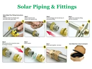
Welding (Fabrication) • Reasonably smooth or arc cutting is accepted. • Boring to align the ends may not result in less than minimum thickness. • Appropriate analysis weld metal may be deposited on the ID or OD to give sufficient metal for machining. • Surfaces shall be clean and free of detrimental material for welding. • Inside diameters shall be aligned as accurately as possible, preferably within 2.0 mm or 1/16 in. • For socket weld, the maximum diameter clearance should be 2.0 mm or 0.80 in. or less. A 1/16-in. bottom gap is required.
Special Considerations for Pipelines (Categories) • Facilities, including compressor/pumping stations and any required storage or control systems to isolate section • Operation and maintenance programs, including reporting and methods of determining the life of the various sections of pipeline • Corrosion control including the transportation of more highly corrosive fluids • Offshore pipeline differences • Managing system integrity of B31.8S, Gas Pipeline Supplement
Special Considerations for Pipelines • Continuous accessibility to the valves • Conservation of gas • Time to blow down the isolated section • Continuity of service • Necessary operating flexibility • Expected future development, which would change the location factor • Significant natural conditions that could have adverse effects