Download

1 / 47
470 likes | 697 Vues
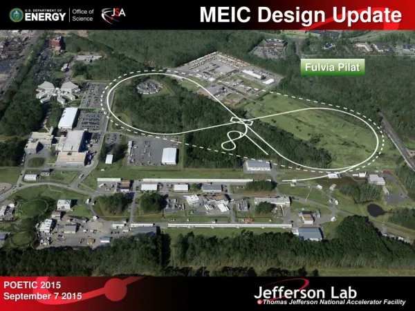
The MEIC Design at Jefferson Laboratory. Fulvia Pilat for the MEIC Study Group EIC Users Meeting Stony Brook, June 24-27, 2014. Outline. Context and updates The MEIC strategy and base of design have not significantly changed in 3+years

E N D
The MEIC Design atJefferson Laboratory Fulvia Pilat for the MEIC Study Group EIC Users Meeting Stony Brook, June 24-27, 2014
Outline • Context and updates The MEIC strategy and base of design have not significantly changed in 3+years The “Science Requirements and Conceptual Design for a polarized MEIC at JLAB” published in 2012 Augmented the JLAB EIC study Group with additional external collaborations Resolved many of the design challenges, working on resolving remaining ones Working to support the NSAC process • MEIC design strategy towards high luminosity and polarization (the full scope of EIC is consistent with an upgrade of the MEIC) • High level status of the design, R&D and remaining challenges • Vision and steps towards a Conceptual Design Report (CDR) • Conclusions and outlook
MEIC Design Report Released Table of Contents Executive Summary Introduction Nuclear Physics with MEIC Baseline Design and Luminosity Concept Electron Complex Ion Complex Electron Cooling Interaction Regions Outlook arXiv:1209.0757
MEIC Design Goals • Energy • Full coverage of √s from 15 to 70 GeV • Electrons 3-12 GeV, protons 20-100 GeV, ions 12-40 GeV/u • Ion species • Polarized light ions: p, d, 3He, and possibly Li • Un-polarized light to heavy ions up to A above 200 (Au, Pb) • At least 2 detectors • Full acceptance is critical for the primary detector • Luminosity • Above 1033 cm-2s-1 per IP in a broad CM energy range • Maximum luminosity >1034optimized to be around √s=45 GeV • Polarization • At IP: longitudinal for both beams, transverse for ions only • All polarizations >70% • Upgrade to higher energies and luminosity possible • 20 GeV electron, 250 GeV proton, and 100 GeV/u ion • Design goals consistent with the White Paper requirements
Ion Source Pre-booster MEIC Layout Ion source Warm large booster (3 to 25 GeV/c) SRF linac Three Figure-8 rings stacked vertically Pre-booster Cold ion collider ring (25 -100 GeV) Warm electron collider ring (3-12 GeV) Medium-energy IPs with horizontal beam crossing Injector 12 GeV CEBAF Linac IP IP MEIC collider rings Full Energy EIC Collider rings • Three compact rings: • 3 to 12 GeV electron • Up to 25 GeV/c proton (warm) • Up to 100 GeV/c proton (cold) 12 GeV 12 GeV CEBAF 11 GeV
Design Strategy for: High Luminosity • The MEIC design concept for high luminosity is based on high bunch repetition rate CW colliding beams KEK-B already reached above2x1034/cm2/s • Beam Design • High repetition rate • Low bunch charge • Short bunch length • Small emittance • “Traditional” hadrons colliders • Small number of bunches • Small collision frequencyf • Large bunch charge n1 and n2 • Long bunch length • Large beta-star • IR Design • Small β* • Crab crossing • Damping • Synchrotron radiation • Electron cooling • Linac-Ring colliders • Large beam-beam parameter for the electron beam • Need to maintain high polarized electron current • High energy/current ERL
Design strategy for High Polarization All rings have a figure-8 shape with critical advantages for both ion and electron beam • Spin precessions in the left & right parts of the ring are exactly cancelled • Net spin precession (spin tune) is zero, thus energy independent • Spin is easily controlled and stabilized by small solenoids or other compact spin rotators Advantage 1: Ion spin preservation during acceleration • Ensures spin preservation • Avoids energy-dependent spin sensitivity for all species of ions • Allows a high polarization for all light ion beams Advantage 2: Ease of spin manipulation • Delivering desired polarization at multiple collision points Advantage 3: The only practical way to accommodate polarized deuterons (ultra small g-2) Advantage 4: Strong reduction of quantum depolarization thanks to the energy independent spin tune This helps to preserve polarization of the electron beam continuously injected from CEBAF
Key design choices • Ring-Ring with CEBAF as a full energy polarized injector • Avoids a class of challenging technology R&D (i.e. high current polarized electron source, high energy high current ERL) • 12 GeV CEBAF source/injector already meets the requirements • Delivers high luminosity and high polarization • We took some conservative technical choices: • Limit key design parameters (beam-beam and space charge parameters) within or close to the present state-of-art • Maximum peak field: SC dipole < 6 T; warm dipole: <1.6 T • Maximum synchrotron radiation power density at 20 kW/m • Manageable final focusing: maximum beta at the final focus quads is 2.5 km
MEIC/EIC e-A luminosity EIC MEIC
MEIC/EIC e- P Luminosity EIC MEIC A. Accardi
Ion Source Prototypes & Parameters Polarized light Ions Non-Polarized Ions Electron-Cyclotron Resonance Ion Source (ECR) Electron Beam Ion source (EBIS) Universal Atomic Beam Polarized Ion Sources (ABPIS) • Numbers in red are “realistic extrapolation for future”; numbers in blue are “performance requirements of BNL EBIS • MEIC ion sources rely on existing and matured technologies • Design parameters are within the state-of-the-art
Ion Linac HWR Normal conducting Superconducting QWR • Pulsed linac, peak power 680 kW • Consists of quarter wave and half wave resonators • Originally developed at ANL as a heavy-ion driver accelerator for Rare Isotope Beam Facility • Adopted for MEIC ion linac because: • Satisfies MEIC ion linac requirements • Covers similar energies, variety of ion species • Excellent and mature design • All subsystems are either commerciallyavailable or based on well-developed technologies
Ion Pre-booster Purpose of pre-booster • Accumulation of ions injected from linac • Acceleration of ions • Extraction and transfer of ions to the large booster Design Concepts • Figure-8 shape • (Quasi-independent) modular design • FODO arcs for simplicity and ease optics corrections Straight 2 Arc 2 Arc 1 Arc 3 Injection Straight 1 • Design constraints • Maximum bending field: 1.5 T • Maximum quad field gradient: 20 T/m • Momentum compaction smaller than 1/25 • Maximum beta functions less than 35 m • Maximum full beam size less than 2.5 cm, • 5m dispersion-free sections for RF, cooling, collimation and extraction.
MEIC Ion Large Booster • Accelerates protons from 3 to 25 GeV (and ion energies with similar magnetic rigidity) • Follow electron/ion collider ring footprints, housed in same tunnel • Made of warm magnets and warm RF • No transition energy crossing (always below γt=25.03) • Quadrupole based dispersion suppression. • Tunable to any working point. Possible to convert the large booster to a low energy collider ring IP • Vertical chicane to bring low energy ions to the plane of the electron ring • Add electron cooling and SRF • Share detector with MEIC
Collider Ring and IR Layout IPs IP ions e- ions e- • Lattice design of geometrically-matched collider rings completed • Detector requirements fully satisfied 20
Detector Region Design small angle hadron detection IP FP (from GEANT4) far forward hadron detection n, g low-Q2 electron detection ion quads large-aperture electron quads ~60 mrad bend p small-diameter electron quads e 50 mrad beam (crab) crossing angle p Fixed trackers in vacuum? Thin exit windows Roman pots central detector with endcaps dual-solenoid in common cryostat 4 m coil 1 m Ion quadrupoles RICH + TORCH? 1 m Endcap barrel DIRC + TOF 2 Tm dipole Electron quadrupoles e/π threshold Cherenkov EM calorimeter Tracking EM calorimeter Trackers and “donut” calorimeter EM calorimeter • Fully-integrated detector and interaction region satisfying • Detector requirements: full acceptance and high resolution • Beam dynamics requirements: consistent with non-linear dynamics requirements • Geometric constraints: matched collider ring footprints 21
MEIC Ion Collider Ring IPs Dog Leg #1 Dog Leg #1 Arc CCB Arc CCB ion R = 90.4 m Arc, 2400 Long straight Arc CCB CCB/dispersion suppressor Arc CCB Dog Leg #2 Dog Leg #2 Detector elements • FODO-cell arcs • CCB in arcs for local chromaticity correction • Vertical doglegs to bring ions to electron plane • With horizontal bend • Dispersion suppression
MEIC Electron Collider Ring Forward e- detection • Flat ring, defines geometry • FODO-cell arcs • All-energy Universal Spin Rotators (USR) • CCB in straights for chromaticity correction IPs USR, 13.2, 54m USR, 13.2, 54m e- R = 90.4 m Arc 445m, 2400 CCB CCB Long straight USR, 13.2, 54m USR, 13.2, 54m 23
Beam Synchronization x = 42.6 cm x = -53.8 cm Total bending angle and z length are fixed • Change the harmonic number of the ion beam at discrete energies (harmonic jump) • Employ two 10 cm path length chicanes (one per arc) between jumps • 10 regular 3 m long arc dipoles per chicane • The green dipoles are regular arc dipoles with fixed bending angles • The bending of the outer and inner red dipoles is adjusted to change the path length • Features • Provides coverage of the full energy range • Automatic synchronization of both IP’s with two chicanes for even number of ion bunches • Requires total additional space of < 20 m (green dipoles are already a part of the arc) • No closed orbit shift (shift the design orbit instead), no SRF frequency change, no CEBAF synchronization issue (electron frequency is fixed), no R&D required • Need to evaluate the engineering challenge of moving cold magnets by up to 50 cm 24
Ion Polarization • Design requirements • High polarization (~80%) of protons and light ions (d, 3He++, and possibly 6Li+++) • Both longitudinal and transverse polarization orientations available at all IP’s • Spin flipping (through the source) • Figure-8 structure as a solution • No preferred periodic spin direction, energy-independent zero spin tune Polarization can be controlled by small magnetic fields • Eliminates depolarization problem during acceleration • Works for all ion species including deuterons • Acceleration and spin matching • Polarization is stabilized by weak (< 3 Tm) solenoids • Injection and extraction from straight with solenoid • Polarization control in the collider ring • Beam is injected longitudinally polarized, accelerated and then the desired spin orientation is adjusted • Weak solenoids for deuterons (< 1.5 Tm each) • Weak radial-field dipoles for protons (< 0.25 Tm each) • Small or no orbit excursions, easy magnet field ramp
Electron Polarization spin arc dipole Solenoid 1 arc dipole Solenoid 2 e- φ1 α1≈8.8º spin φ2 α2≈4.4º Lost or Extracted P0 (>Pt) Pt • Design requirements • High polarization (>80%) and sufficient life time • Longitudinal polarization at all interaction points • Spin flipping (through the source) at required frequencies • Highly vertically polarized electron beam is injected from CEBAF • Polarization is vertical in the arc to avoid spin diffusion • Universal spin rotator rotates polarization from vertical to longitudinal at IP • Spin flipping through the source • Compton polarimeters to measure polarization • Continuous injection is considered to maintain high polarization at higher energies • Figure 8 structure removes electron spin tune energy dependence
Multi-Staged e-Cooling Scheme large booster (25 GeV) medium energy collider ring pre-booster (3 GeV) (accumulation) DC cooling High Energy cooling ion sources SRF Linac state-of-the-art
Cooling Technology Staging • The “ready-to-build” version utilizes only (loosely speaking) existing and established accelerator technologies
Luminosity at different cooling stages Based on existing technologies EICAC recommendation 5.6 Add “weak” electron cooling & stochastic cooling (heavy ions) during collision Full capacity electron cooling (ERL-circulator cooler) Luminosity (1033 1/cm2/s) ~3.3 Low energy DC cooling only at pre-booster injection Add 3 GeV DC cooling at pre-booster ~1.1 ~0.41
Plans towards CDR Jefferson Lab plans to have a comprehensive Conceptual Design Report in 2-3 years • Resources: Manpower: • Given competing priorities MEIC design and R&D have operated at the 5-6 FTE level at JLAB plus leveraged collaborations • The end of 12 GeV Project accelerator scope (12 GeV experiment till 2017 and the integration of FEL personnel in Accelerator and Engineering significantly increased manpower in 2014 • Pursuing new collaborations MEIC Design and R&D funding: • NP grants (mainly towards supporting 3 post-docs) • Commonwealth of Virginia funding • LDRD (fast kicker R&D) • SBIR (Tech-X) • JLAB Accelerator R&D funds
Plan for cost estimate • A preliminary (“not ready for review” ) cost estimate for MEIC was carried out in 2012 • A task force to issue a cost estimate for MEIC has been appointed at JLAB in January 2014 and is working now. The task force includes senior management from the 12 GeV Project, the Accelerator and Engineering Divisions, with support from the Project Management Group. • A comprehensive MEIC WBS to level 5 • Baseline (Base of estimate) – June 2014 • Engineering study - July 2014 • Cost estimate – September-October 2014
Towards a Conceptual Design Report Existing Design Report Design Optimization Detector R&D Report on Detector /IR Design Studies MEIC Conceptual Design Report Report on High Energy Electron Cooling Accelerator R&D 2MeV DC Cooler Technical Design Report Report on Beam Polarization Design
Accelerator Team & Current Collaboration • Core team (CASA): A. Bogacz, Y. Derbenev, D. Douglas, R. Li, R. Kazimi, G. Krafft, F. Lin, V. Morozov, Y. Roblin, M.Spata, C. Tennant, M. Tiefenback, H. Zhang, Y. Zhang, students (C-Y Tsai , A. Castilla) • RF systems: F. Hannon, R. Rimmer, H. Wang, S. Wang (SRF R&D, Jlab) • RF Fast Kicker: A. Kimber (Engineering), C. Tennant LDRD • High current un-polarized e-source: R. Suleiman (Source, Jlab) • Interaction regions: M. Sullivan (SLAC) • Polarization: A. Kondratenko (Novosibirsk), D. Barber (DESY) • Low energy ion complex: linac: P. Ostroumov (Argonne Lab) pre-booster: B. Erdelyi (Northern Illinois Univ.) • Beam-beam simulation: J. Qiang (LBL) • Cooling Simulation: I. Pogorelov (Tech-X) SBIR • Nonlinear corrections, DA: D. Trbojevic, Y. Jing, Y. Luo (BNL) U. Wienands, Y. Nosochkov (SLAC)
Conclusions and outlook • The MEIC design fulfills the requirements for high luminosity and polarization needed by the nuclear physics community • We have a mature strategy and design and a very significant progress has been achieved on technical challenges in the last 3 years We need to: • Demonstrate the remaining open technical issues with studies, modeling and a strategic and collaborative R&D program • Strengthen further the Design Team at Jefferson Lab as well as widen the external collaboration • Secure R&D funding commensurate with the stated goals • We believe we can deliver a comprehensive Conceptual Design Review in 2-3 years
Electron polarization • electron beams with high polarization are injected from CEBAF • avoid spin decoherence, simplify spin transport from CEBAF to MEIC, alleviate the detector background • Polarization is designed to be vertical in the arc to avoid spin diffusion and longitudinal at collision points using spin rotators • A Universal spin rotator rotates the electron polarization from 3 to 12GeV • spin flipping is implemented by changing the source polarization • A Compton polarimeter is considered for polarization measurements • Two long opposite polarized bunch trains (instead of alternate polarization between bunches) simplify the Compton polarimetry • The figure-8 geometry removes electron spin dependence on energy • Continuous injection of electron bunch trains from the CEBAF is envisioned to • preserve and/or replenish the electron polarization, especially at higher energies, and • maintain a constant beam current in the collider ring • Spin matching in some key regions is considered if it is necessary … bunch train & polarization pattern in the collider ring 1.33ns 748.5MHz Empty buckets Empty buckets … … … Polarization (Down) Polarization (Up)
Why a magnetized electron cooler? • With the cathode immersed in a solenoid, the gun generates an almost parallel (laminar) beam state of a large size • Larmor circles very small compared to the beam size • This state is then transported to the solenoid in the cooling section • Conserves the canonical emittances • The solenoid field is chosen to make the electron beam size match properly the ion beam size Magnetization results in the following critical advantages (compared to a non-magnetized gun): • Large reduction (by two orders of value) of (local and global) space charge • Improves the dynamics in CCR (tune shift, micro-bunching) • Strong suppression of CSR micro-bunching/ energy spread growth • Limits reduction of cooling rates due to high electron transverse velocity spread and short-wave misalignments • Ion collides with “frozen” electrons
Continuous Injection Technique • Continuous injection principle • Note that: • Continuous injection mainly considered at higher energies • A relatively low averaged beam current of tens-of-nA level • Constant beam current maintained • On possible injection bunch pattern 2.3μs, ~1700 bunches …… 1.33 ns, 748.5 MHz …… 2.4 pC 2.4 pC …… 2.3μs, ~1700 bunches 1.33 ns, 748.5 MHz Lost or Extracted 1 ms Iave = 59 nA P0 (>Pt) 140 ms Pt
EICAC Meeting 2/28/14 MEIC Nominal Parameters at Design Point 100X5 GeV2
MEIC Nominal Parameters at Design Point 50X5 GeV2 EICAC Meeting 2/28/14
MEIC Nominal Parameters for Lead Ion at Design Point 40X5 GeV2 EICAC Meeting 2/28/14
Priorities for Optimizing Scientific Output FY16-20(M$) EICAC Meeting 2/28/14
EICAC Meeting 2/28/14 Universal Spin Rotator • Rotating spin from vertical to longitudinal • Consists of 2 solenoids & 2 (fixed angle) arc dipoles • Universal • energy independent • works for all energies (3 to 12 GeV) • orbit independent • does not affect orbital geometry Compensation of solenoid x-y coupling V. Livinenko & A. Zholents, 1980 spin arc dipole Solenoid 1 Solenoid 2 arc dipole Electron beam φ1 α1≈8.8º spin φ2 α2≈4.4º solenoid 4.16 m solenoid 4.16 m decoupling quad insert Sayed, Bogacz
EICAC Meeting 2/28/14 Proton/He-3 Polarization at IPs Case 1: Longitudinal Proton Polarization at IP’s • Three Siberian snakes, all longitudinal-axis • Third snake in straight is for spin tune • Spin tune: 1/2 longitudinal axis Case 2: Transverse proton polarization at IP’s Vertical axis • Three Siberian snakes, both in horizontal-axis • Vertical polarization direction periodic • Spin tune: 1/2 Case 3: Longitudinal & transverse proton polarization on two straights longitudinal • Two Siberian snake, with their parameters set at specific values. Spin tune: 1/2 Vertical axis in special angle
EICAC Meeting 2/28/14 Deuteron Polarizations at IPs Case 1: Longitudinal Deuteron Polarization at IP’s • Stable spin orientation can be controlled by magnetic inserts providing small spin rotation around certain axis and shifting spin tune sufficiently away from 0 • Polarization is stable as long as additional spin rotation exceeds perturbations of spin motion • Polarization direction controlled in one of two straights • Longitudinal polarization in a straight by inserting solenoid(s) in that straight Solenoid Case 2: Transverse Deuteron Polarization at IP’s Insertion • Magnetic insert(s) in straight(s) rotating spin by relatively small angle around vertical axis (A. Kondratenko)