Muxes and Encoders
220 likes | 715 Vues
Muxes and Encoders. Shannon’s Expansion. e . = 0. x . f . e . e . = 1. x . f . x . f . Tri-State Buffers A tri-state buffer has one input x, one output f and one control line e Z means high impedance, i.e. no output at all. Equivalent circuits. normal tri-state buffer symbol.

Muxes and Encoders
E N D
Presentation Transcript
Muxes and Encoders Shannon’s Expansion
e = 0 x f e e = 1 x f x f • Tri-State Buffers • A tri-state buffer has one input x, one output f and one control line e • Z means high impedance, i.e. no output at all Equivalent circuits normal tri-state buffer symbol
e e f f x x e e f f x x • Other Types of Tri-State Buffers active high, not inverted active high, inverted output is enabled (connected) when e = 1 active low, not inverted active low, inverted output is enabled (connected) when e = 0
w f 0 s w 1 • 2x1 MUX Using Tri-State Buffers • Tri-state buffers can be used in place of SOP form • Note – this is the one case where the output lines can just be “tied together” • The control line s selects which buffer will pass its input
s x y 1 1 x y 2 2 • Crossbar Switch • A crossbar switch connects any input to any output • A 2x2 crossbar connects 2 inputs to 2 outputs • You can route each input straight thru, or cross them • When s = 0, y1 = x1 and y2 = x2 (no switching) • When s = 1, y1 = x2 and y2 = x1 (switched)
x 0 1 y 1 1 s x 0 2 y 2 1 • 2x2 Crossbar Switch Using MUXes • A 2x2 crossbar can be constructed from 2x1 MUXes
Using MUXes for Synthesis • MUXes are very significant combinational devices • MUXes are a key component of FPGAs (field programmable gate arrays) – to be discussed soon • MUXes can be used to synthesize any combinational logic function • Makes use to Shannon's expansion
Shannon's Expansion • Any Boolean function f(w1,w2,…,wn) can be written in the form f(w1,w2,…,wn) = w1' f(0,w2,…,wn) + w1 f(1,w2,…,wn) • w1 acts as the selector control input and it selects between f(0,w2,…,wn) and f(1,w2,…,wn) • f(0,w2,…,wn) is called the cofactor of f with respect to w1' • f(1,w2,…,wn) is called the cofactor of f with respect to w1 • Example: f(w1,w2,w3) = w1w2 + w1w3 + w2w3 • w1' f(0,w2,w3) + w1 f(1,w2,w3) = w1' (w2w3) + w1 (w2 + w3)
w 1 w 2 w 3 0 f 1 • MUXes Based on Shannon's Expansion • f(w1,w2,w3) = w1' (w2w3) + w1 (w2 + w3) is implemented using a 2x1 MUX as follows …
0 1 • More Shannon's Expansion Examples • f(w1,w2,w3) = w1'w3' + w1w2 + w1w3 • Expand on w1: • f(w1,w2,w3) = w1' f(0, w2,w3) + w1f(1,w2,w3) = w1' (w3') + w1(w2 + w3) • Use a 2x1 MUX
Same Example …. • f(w1,w2,w3) = w1'w3' + w1w2 + w1w3 • Expand on both w1and w2: • f(w1,w2,w3) = w1'w2'f(0,0,w3) + w1'w2f(0,1,w3) + w1w2'f(1,0,w3) + w1w2f(1,1,w3) = w1'w2'(w3') + w1'w2(w3') + w1w2'(w3) + w1w2(1) • Use a 4x1 MUX
Implementing Using Only MUXes • Shannon's expansion can be used to implement functions using MUXes exclusively • Example: f(w1,w2,w3) = w1w2 + w1w3 + w2w3 • Use 2x1 MUXes only to implement this • Expanding on w1 • f(w1,w2,w3) = w1'(w2w3) + w1(w2+w3+w2w3) • Let g = w2w3 • Let h = w2+w3+w2w3
w w 2 1 0 w 3 f 1 • Example Continued … • f(w1,w2,w3) = w1'(g) + w1(h) • where g = w2w3 • where h = w2+w3+w2w3 • Expanding g on w2 gives g = w2'(0) + w2(w3) • Expanding h on w2 gives h = w2'(w3) + w2(1)
w 2 w 1 0 w 3 f 1 • Last Example: Use Only a 4x1 MUX • Try this one: f(w1,w2,w3) = m(3,5,6,7) • f = w1'w2w3 + w1w2'w3 + w1w2w3' + w1w2w3 • Use a 4x1 MUX by expanding on both w1and w2 • f = w1'w2'(0) + w1'w2(w3) + w1w2'(w3) + w1w2(1)
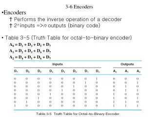
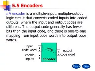
7 6 5 4 3 2 1 0 w 0 y 0 n n 2 outputs inputs y n – 1 w n 2 – 1 • Encoders • The opposite of decoding is encoding • Encoder encodes one-asserted information • An 2n bit one-hot value is presented as input • A binary encoded output of size n is the result • Example: input is 01000000 output is 110 (i.e. 6)
w 0 w 1 w y 2 0 w 3 y 1 • 4 to 2 Encoder • A 4 to 2 encoder encodes a 4 bit one-hot input into a 2 bit binary encoded output
Building Encoders • Notice that since the input is guaranteed to be one-hot, the design of an encoder is simple • y1 = w3 + w2 • y0 = w3 + w1 • Each output signal y is just the sum of the input signals that are asserted for the “on set” of y • These encoder types are called binary encoders
Priority Encoders • What if you can’t guarantee, or don’t want to guarantee, that the input is one-hot? • You can encode the input with the highest priority • Priority can be assigned in many ways • One priority scheme is to pick the input lines in order according to position • Example: input is 01100100 output is 110 since line 6 is “more significant” than line 5 or line 2 • What if input is 00000000? Compare to 00000001? 7 6 5 4 3 2 1 0
4 to 2 Priority Encoder • 4 input lines (w3:w0) • w3 has highest priority; w0 has lowest priority • 2 output lines (y1:y0) • 1 “valid” (z) output to determine if any line is active at all
Logic for Priority Encoders • Let i0 = w3'w2'w1'w0 i1 = w3'w2'w1 i2 = w3'w2 i3 = w3 • Then y0 = i1 + i3 y1 = i2 + i3 • z = i0 + i1 + i2 + i3 same structure as one-hot encoder: sum of terms in the on set
74147 Priority Encoder • All inputs are active low • All outputs are active low • 0110 is "9" • 1110 is "1"