Download
1 / 31
310 likes | 512 Vues
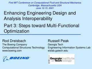
First MIT Conference on Computational Fluid and Structural Mechanics Cambridge, Massachusetts USA June 12-15, 2001. Enhancing Engineering Design and Analysis Interoperability Part 3: Steps toward Multi-Functional Optimization. Rod Dreisbach The Boeing Company

E N D
First MIT Conference on Computational Fluid and Structural Mechanics Cambridge, Massachusetts USA June 12-15, 2001 Enhancing Engineering Design and Analysis InteroperabilityPart 3: Steps toward Multi-Functional Optimization Rod Dreisbach The Boeing Company Computational Structures Technology www.boeing.com Russell Peak Georgia Tech Engineering Information Systems Lab eislab.gatech.edu
Typical Current Approach: Optimize idealized parameters (vs. detailed design) G1 : b = cavity3.inner_width + rib8.thickness/2 + rib9.thickness/2 ... Need fine-grained CAD-CAE associativity G Idealizations “It is no secret that CAD models are driving more of today’s product development processes ... With the growing number of design tools on the market, however, the interoperability gap with downstream applications, such as finite element analysis, is a very real problem. As a result, CAD models are being recreated at unprecedented levels.” Ansys/ITI press Release, July 6 1999 http://www.ansys.com/webdocs/VisitAnsys/CorpInfo/PR/pr-060799.html = K f ( r , b , h ) 3 1 P P = f C = f be 1 2 ht se p 2 r t e 0 e Detailed Design Model Analysis Model (with Idealized Features) Channel Fitting Analysis
Multi-Functional Optimization (MFO) • Term as coined at Boeing • Multitude of operational functional requirements • Concurrent consideration during product design process • Idealized design variables used in optimization associated directly with product (detailed design)
Progress onNecessary Components • Design-Analysis Integration • CAD-CAE Associativity • Connect diverse CAE models to same CAD model: Varying discipline, behavior, fidelity, method, tool • Multi-directional • Object-Oriented View of Optimization • Enhanced FEA Modeling for Built-Up Structure
X-Analysis Integration Techniques a. Multi-Representation Architecture (MRA) b. Explicit Design-Analysis Associativity c. Analysis Module Creation Methodology
COB-based Constraint Schematic for Multi-Fidelity CAD-CAE InteroperabilityFlap Link Benchmark Example
Test Case Flap Linkage: Analysis Template Reuse of APM deformation model linkage L al1 effective length, eff mode: shaft tension cross section area, A al2 L A t s2 t material linear elastic model youngs modulus, E al3 s1 q s reaction condition Sleeve 2 Sleeve 1 Shaft d s1 d s2 A L stress mos model eff Extensional Rod (isothermal) D L L o allowable stress x L 1 x 2 A s E e F Margin of Safety (> case) allowable actual MS Linkage Extensional Model (CBAM) Flap link (APM) reusable idealizations
Flap Link APMImplementation in CATIA v5 Design-Idealization Relation Design Model Idealized Model
CATDAK OverviewXaiToolsCATIA Design-Analysis Knowledge Manager Design & Idealizations (APM) CAD-Analysis Template Coordination Analysis Template Usage (CBAMs) CATDAK XaiTools Analysis Inputs CATIA Model API VBScripts Analysis Outputs (Design Updates) VBScripts Analysis Templates Traditional Solvers API = application programming interface
Progress onNecessary Components • Design-Analysis Integration • CAD-CAE Associativity • Connect diverse CAE models to same CAD model: Varying discipline, behavior, fidelity, method, tool • Multi-directional • Object-Oriented View of Optimization • Enhanced FEA Modeling for Built-Up Structure
Partition of Engineering Entities 1 æ ö c ç p ÷ e ç ÷ D 1 N ç ÷ = 2 f ' ç ÷ 2 e ç ÷ f è ø Enhanced Optimization Model (EOM) Engineering Math Opt Model Opt. Model Solution Method Model Find Design variable Notation solder joint height(h) (a ) PWB material type Maximize : Solder Fatigue life THESIS FOCUS Context-Based Analysis Model Analysis Building Block Printed Wiring Assembly (PWA) Solution Method Model Solder T body Component Component 0 1 Joint body body Solder Joint 4 3 body PWB 2 Printed Wiring Board (PWB) Previous work Analyzable [Peak et al. 2000, Analysis Tools Product Model 1999, Tamburini Design Tools Wilson, 2000]
Optimization Model Diversity OPTIMIZATION MODEL CLASS Optimization Object 1 Optimization Object 2 Min Weight Min Weight subject to subject to Stress Buckling Design variables Area, Material Stress Design variables Area 1D EXTENSIONAL STRESS MODEL Analysis Model(s) Enhancement and/or Addition Objective, design variable, and/or constraint function enhancement OPTIMIZATION MODEL CLASS Optimization Object 1 Optimization Object 2 Optimization Object 3 Min Weight Min Weight, Cost Min Weight subject to subject to subject to g (x)<0 g (x)<0 g (x)<0 h(x) =0 h(x) =0 h(x) =0 X(H) X(H,LL,LR) X(H,LL,LR,Mat) 2D PLANE STRAIN MODEL
Optimization Model Enhancement = r f LA 1 = ³ g MS ( A ) 0 1 stress = r f LA 1 = ³ g MS ( A ) 0 1 stress OPTIMIZATION MODEL I Minimize Weight Subject to Normal Stress Margin of Safety Design variables X ={A} OPTIMIZATION MODEL II Minimize Weight Subject to Normal Stress Margin of Safety Design variables X ={A, material}
Minimization of Weight of a LinkageX(area) subject to (extensional stress) L A t s2 t y s1 L q s D L L eff Sleeve 2 Sleeve 1 Shaft P P e s x E, A , d s1 d s2 A L eff = r W AL Margin of Safety (> case) allowable actual MS ³ MS 0 deformation model Extensional Rod (isothermal) analysis context product structure: linkage L al1 effective length, eff D L L o x L 1 x 2 mode: shaft tension cross section area, A al2 A material linear elastic model youngs modulus, E al3 condition: linkage s E density, r flaps down reaction e F goal: optimization minimize weight weight,W constraint allowable stress s L eff MSstress Design Variable A
Minimization of Weight of a LinkageX(area, material) subject to (extensional stress) L A t s2 t y s1 L q s D L L eff Sleeve 2 Sleeve 1 Shaft P P e s x E, A , d s1 d s2 A L eff = r W AL Margin of Safety (> case) allowable actual MS ³ MS 0 deformation model Extensional Rod (isothermal) analysis context product structure: linkage L al1 effective length, eff D L L o x L 1 x 2 mode: shaft tension cross section area, A al2 A material linear elastic model youngs modulus, E al3 condition: linkage s E density, r flaps down reaction e F goal: optimization minimize weight weight,W constraint allowable stress s L eff MSstress Design Variable area,A material
Optimization Model Enhancement = r f LA 1 = ³ g MS ( A ) 0 1 stress = ³ g MS ( A ) 0 2 buckling OPTIMIZATION MODEL III OPTIMIZATION MODEL IV Minimize Weight Subject to Normal Stress Margin of Safety Buckling Margin of Safety Design variables X ={A, material}
Minimization of Weight of a LinkageX(area) subject to (extensional stress, buckling load) L A t s2 t y s1 L q s D L L eff Sleeve 2 Sleeve 1 Shaft P P e s x E, A , d s1 d s2 A L eff = r W AL Margin of Safety Margin of Safety (> case) (> case) allowable allowable actual actual MS MS ³ MS 0 deformation model Extensional Rod (isothermal, buckling) analysis context product structure: linkage L effective length, eff D L L o x L I moment of inertia, 1 x cross section 2 mode: shaft tension area, A A material linear elastic model youngs modulus, E condition: linkage s E density, r flaps down reaction load,P e F goal: optimization minimize weight Extensional Rod weight,W (Buckling) constraints L o E P s cr I allowable stress L eff MSstress MSbuckling Design Variables A
Minimization of Weight of a LinkageX(area, material) subject to (extensional stress, buckling load) L A t s2 t y s1 L q s D L L eff Sleeve 2 Sleeve 1 Shaft P P e s x E, A , d s1 d s2 A L eff = r W AL Margin of Safety Margin of Safety (> case) (> case) allowable allowable actual actual MS MS ³ MS 0 deformation model Extensional Rod (isothermal, buckling) analysis context product structure: linkage L effective length, eff D L L o x L I moment of inertia, 1 x cross section 2 mode: shaft tension area, A A material linear elastic model youngs modulus, E condition: linkage s E density, r flaps down reaction load,P e F goal: optimization minimize weight Extensional Rod weight,W (Buckling) constraints L o E P s cr I allowable stress L eff MSstress MSbuckling A Design Variables material
Progress onNecessary Components • Design-Analysis Integration • CAD-CAE Associativity • Connect diverse CAE models to same CAD model: Varying discipline, behavior, fidelity, method, tool • Multi-directional • Object-Oriented View of Optimization • Enhanced FEA Modeling for Built-Up Structure
Chip Package Products Shinko Quad Flat Packs (QFPs) Plastic Ball Grid Array (PBGA) Packages
VTMB = variable topology multi-body Traditional VTMB FEA Model CreationManually Intensive: 6-12 hours FEA Model Planning Sketches - EBGA 600 Chip Package
Advanced Product Information-Driven FEA Modeling: Challenges Main challenges • Differences between design & analysis geometries • Variable topology multi-body geometries • FEA requirements: node matching, aspect ratio • Relative body sizes • Degree of indirect inter-body coupling • Mixed analytical bodies • Idealized inter-body interfaces • Loads & interfaces on non-explicit boundaries • Idealization-induced anomalies • Ex. - Shell mid-/outer-face matching • Arbitrary shapes (complex 3D surfaces …)
Multi-Representation Architecture Context • Composed of four representations (information models) • Provides flexible, modular mapping between design & analysis models • Creates automated, product-specific analysis modules (CBAMs) • Represents design-analysis associativity explicitly
Approach Outline: Test Cases • Benchmark test cases • “diving board” • eWidget • simplified PBGA • Production test cases(representative production-like problems for industry) • Chip package (Shinko) • Thermal analysis - Phase 2 • Thermomechanical (stress) analysis - after Phase 2 • Air frame structural analysis (Boeing) • PWA/B (JPL/NASA,…) • Thermomechanical, ...
Airframe Structural AnalysisRadar Support Structure(for Boeing) Design Model Automatic FEA Pre/Post-processing & Solution (in vendor-specific Solution Method Model)
PWA Thermomechanical Analysis(for JPL/NASA, ...) Goal: Generalization of previous work [Zhou, 1997]
Summary Progress … • Design-Analysis Integration (maturing) • CAD-CAE Associativity • Connect diverse CAE models to same CAD model: Varying discipline, behavior, fidelity, method, tool • Multi-directional • Object-Oriented View of Optimization (initial progress) • Enhanced FEA Modeling for Built-Up Structure (in-progress) Further work needed … • High-level operational criteria, such as Product Design Requirements and Objectives • Need to leverage recent optimization tools • Ex. iSIGHT, ProductCenter, etc. • Provide enhanced modularity & knowledge capture