Download
1 / 16
160 likes | 345 Vues
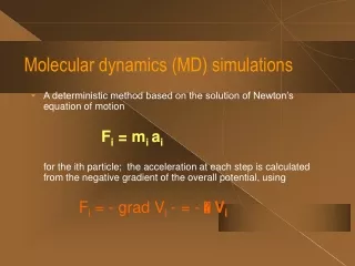
Study on C-W interactions by Molecular Dynamics Simulations. Zhongshi Yang , Q. Xu, G. -N. Luo Institute of Plasma Physics, Chinese Academy of Sciences, Hefei 230031, China. G. -H. Lu Department of Physics, Beihang University, Beijing 100083, China. Outline. Background Simulation Method

E N D
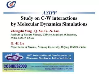
Study on C-W interactions by Molecular Dynamics Simulations Zhongshi Yang , Q. Xu, G. -N. Luo Institute of Plasma Physics, Chinese Academy of Sciences, Hefei 230031, China G. -H. Lu Department of Physics, Beihang University, Beijing 100083, China
Outline • Background • Simulation Method • Range distribution • Points defects • Conclusion
W as PFM W: A suitable candidate plasma facing material for limiters and divertors of thermalnuclear fusion reactors • good thermal conductivity • high temperature strength • high energy threshold for physical sputtering • high melting point • low vapour pressure
C- W Mixing • carbon based materials: widely used in fusion devices as PFM. • The divertor PFM of ITER: a combination of C and W • mixing with C on the W surface: • carbon based materials are easy to be eroded and the eroded C atoms will generally migrate to other locations due to long range plasma transport processes and interact with the W surface. • it is necessary to understand and predict the W surface properties and performance in the presence of C impurities. • further understanding co-depostion of carbon and hydrogen on W surface and the hydrogen inventory in W.
Summary of C-W interactions • experimental data: • confined in the C projectiles with high energy of keV interacting with W • Simulations: • based on the binary collision approximation and adopted amorphous target materials • this work: • the molecular dynamics (MD) simulations • bond-order interatomic potential*: for modeling the ternary W–C–H system • Focus on: • surface effect, projected range distribution of C atoms with different incident energy on W surface. • point defects in W: vacancy and interstitial C atoms as well as their mutual interactions *N. Juslin, et al, J. Appl. Phys. 98 (2005) 123520
Simulation Method • The initial computational cell: • (001) plane normal to the incidence direction, • dimension of 63.31 Å × 63.31 Å × 31.65 Å, consisting of 8000 atoms. • Periodic boundary conditions imposed in the x and y directions. the atoms in the lowest three atomic layers kept fixed . • MD steps are changed according to the kinetic energy of the incident C atoms. • The BOP is used to describe the W-W and W-C interactions. • C projectiles: • a series of kinetic energies from 0.5 eV to 200 eV, • z0 greater than the potential cutoff radius, initial x0 and y0 randomly selected above the cell. • overall 200 runs performed to obtain significant statistics For a given incident energy
Amorphous W cell • simulated annealing process: • The initial structure: random cell consisting of 8000 W atoms, a density of 19.25 g/cm3, periodic boundary conditions applied along the three directions • The system was first heated to 4000 K. Once molten, the sample was equilibrated at 4000 K for 200 ps. The liquid sample was then cooled to 300 K with a linear cooling rate of 40 Kps-1. Finally, the system was equilibrated at 300 K for an additional 50 ps to anneal away any transient structures • The first-neighbor peak is corresponding to the first-neighbor peak in the crystalline tungsten cell indicating the short-range order in the amorphous cell. • The second peak shifts along the distance and more high-order peaks become broader and less well defined with increasing distance meaning the absence of long-range order. The W-W pair distribution function g(r) for the simulated amorphous cell in comparison with the crystalline sample.
Surface damage Snapshots of the simulation cells after successive 50 incident energetic projectiles’ bombardment at 1 eV (b) 5 eV (c) 10 eV (d) 50 eV (e) 100 eV (f)200 eV *red balls represent the C atoms *black ones represent W atoms. • The amorphization in the top few layers is pronounced with increasing incident energy. • The kinetic energy of the projectiles is released through fast collisions with contiguous lattice atoms hence the increase of temperature in the impact area and vibration amplitude of lattice atoms.
Reflection • At 10 eV incident energy, the reflection coefficient (RC) has a largest value near to unity. • Above 10 eV, the RC decreases monotonically with increasing incident energy because the energetic projectile has larger probability to be implanted into the tungsten bulk. • Below 10 eV, the RC decreases with incident energy and the projectiles have a larger probability to stick on the tungsten surface. • The energy reflection upon incident energy has a similar trend to the particle reflection. (a) Particle and (b) energy reflection coefficients of normal incident carbon atoms on two types of tungsten surfaces, bcc tungsten (001) surface and amorphous tungsten surface, as a function of incident energy. Eckstein’s results* calculated by TRIM.SP are also displayed. The statistical uncertainties are covered by the graphical markers. * W. Eckstein, Calculated Sputtering, Reflection and Range Values, IPP 9/132, 2002
Projected range distribution Average depth (mean range) of atomic carbons implanted in crystalline tungsten at normal incidence on (001) tungsten surface and amorphous cell surface as a function of incident energy. The results calculated by Eckstein using TRIM.SP code are also shown. • Below 10 eV, the un-scattered C atoms are absorbed on the top layer and can not penetrate into the bulk. • Near 10 eV, the incident atoms have largest probability to be back-scattered from the surface. • Above 10 eV, the energetic projectile has larger probability to be implanted into the W bulk and the rangemean range increases as well as the range straggling. • Around the energy of 50 eV, the mean range for the crystalline surface exceeds the result for the amorphous surface which may be attributed to the channeling effect. The projected range distribution of atomic C with different incident energy on W (001) surface: (a) 1eV, (b) 5 eV, (c) 10 eV, (d) 50 eV,(e) 100 eV.
Channeling Time variation of the kinetic energy and projected range of the channeled projectile with incident kinetic energy 150eV in W bulk • In the range of incident energy of 50-200 eV, channeling occurs along the <001> crystallographic axis. • Before 50 fs, the atom does not make close-impact collisions with lattice atoms and has a very low rate of kinetic energy loss, dE/dx, and slight vibration with small amplitude. • When the ion penetrates beyond 20th atomic layers after 50 fs, the incident ion is subjected to intense nuclear stopping. The kinetic energy decreases dramatically and starts to vibrate with great amplitude through successive collisions with lattice atoms and in the end the ion comes to rest in the bulk. Channeled trajectoryof C atom at Ein=150eV in the W bulk
Point defects calculation • Bombardment of crystalline W surface with energetic atoms produces regions of lattice disorder • the defects of vacancy and interstitial C atom in bcc W are investigated using MD calculations • Ev = E((N-1)W) - (N-1)Eref(W) • Eint = E(NW + C) - NEref (W) - Eref (C) • Esub = E((N-1)W + C) - (N-1)Eref (W) - Eref (C) • Eb(V-C) = Ef (V) + Ef (C) – Ef (V-C)
Interstitial configuration • The formation energies for the octahedral site: 2.57 eV • The formation energies for the tetrahedral site: 2.91eV • The migration energy for the interstitial C atom from octahedral to neighboring octahedral site through the tetrahedral saddle point 0.34 eV • the C atoms prefer occupying the octahedral to the tetrahedral interstitial sites in agreement with previous study based on the concept of elastic dipole * (A) the octahedral and (B) the tetrahedral interstitial sites in bcc W lattice * Gmelin Handbook of Inorganic Chemistry, 8 ed., Syst. No. 54, Tungsten, Suppl. Vol. A2, Spring-Verlag, Berlin, Heidelberg, New York, Tokyo, 1987.
Structural response of the W lattice to the presence of interstitial C atom • The relative distance of the first neighbors of C increases by a factor ⊿d1/d1 = 0.236 along the <100> direction • The second neighbors are slightly decreased by a factor ⊿d2/d2 = 0.015 along the <110> direction • These deformations are attributed to energy difference during the system relaxation The lattice distortion around the C atom in Oh configuration *the dash balls denoted the original positions of the lattice W atoms and octahedral interstitial C atom *the solid balls represent the ultimate configuration after sufficient structure relaxation
Conclusions • The interaction between low-energy atomic C with W surface has been studied by MD simulations using a bond-order potential. • Both particle and energy reflection coefficients are calculated as a function of incidentenergy in the in the range from 0.5eV to 200eV. • Mean range and projected range distribution of C with different incident energy on tungsten surface are discussed. • Vacancy formation energy and the migration energy, C interstitial and substitutional formation energies have been calculated. • Most stable configuration of an interstitial C atom in W is in Oh position;Lattice distortion around the C atom in Oh configuration occurs along <100> and <110> directions