Arduino
910 likes | 1.91k Vues
Arduino. Introduction to the Arduino. The Arduino. • Introduction to Arduino. • Setting up your Arduino Environment. • Your first Arduino sketch. • Basic digital & analog output control. • Basic digital sensor inputs. • Making LEDs glow and blink on command.

Arduino
E N D
Presentation Transcript
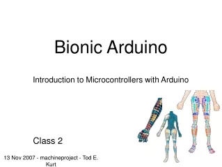
Arduino Introduction to the Arduino
The Arduino • Introduction to Arduino • Setting up your Arduino Environment • Your first Arduino sketch • Basic digital & analog output control • Basic digital sensor inputs • Making LEDs glow and blink on command • How to read buttons & switches
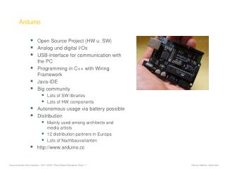
Whats it For ? • The Arduino is a Computer – a small computer • It can run software you write on your PC – same language as Processing • You can control real world hardware • lights, motors other computers • You can read data from real world hardware • Temperature sensors, accelerometers • GPS • A lot of things • Can add more things called shields • network, USB, GPS, LCD Screens, Touch Screen • Good to learn whats in your cell phone, XBOX, Wii, PC/Mac, iPadetcetcetc
A Word on Safety • Electronics can hurt you • Lead in some of the parts • Wash up afterwards • You can hurt electronics • Static-sensitive: don’t shuffle your feet & touch • Wires only bend so much
What is Arduino? The word “Arduino” can mean 3 things A programming A physical piece A community environment of hardware & philosophy
Arduino Philosophy & Community • Open Source Physical Computing Platform • “open source hardware” • open source: free to inspect & modify • physical computing. er, what? ubiquitous computing, pervasive computing, ambient intelligence, calm computing, everyware, spimes, blogjects, smart objects... • Community-built • Examples wiki (the “playground”) editable by anyone • Forums with lots of helpful people
Arduino Hardware • Similar to Basic Stamp (if you know of it) • but cheaper, faster, & open • Uses AVR ATmega168 microcontroller chip • chip was designed to be used with C language The designer of the AVR purposefully arranged its registers and instruction set so that C programswould compile efficiently on it. This is a big deal, compared to previous microcontrollers where Cprograms were almost always less efficient than a hand-coded assembly language variant.
Arduino Hardware Variety LilyPad DIY (for clothing) USB Boarduino Kit “Stamp”-sized Bluetooth many different variations to suite your needs Openness has its advantages, many different varieties. Anyone can build an Arduino work-alike in any form-factor they want.Product images from Sparkfun.com and Adafruit.com
Arduino Capabilities • 16 kBytes of Flash program memory • 1 kByte of RAM • 16 MHz (Apple II: 1 MHz) • Inputs and Outputs • 13 digital input/output pins • 5 analog input pins • 6 analog output pins* • Completely stand-alone: doesn’t need a computer once programmed * only sorta analog, uses PWM , which we’ll talk about later. Don’t worry if the above doesn’t make sense, you don’t really need to know it.
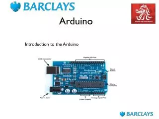
Arduino Diecimila/Uno Board Power LED ATmega168 2.7”
Arduino Terminology “sketch” - a program you write to run on an Arduino board “pin” - an input or output connected to something. e.g. output to an LED, input from a knob.“digital” - value is either HIGH or LOW. (aka on/off, one/zero) e.g. switch state“analog” - value ranges, usually from 0-255. e.g. LED brightness, motor speed, etc.
Arduino Software • Like a text editor • View/write/edit sketches • But then you program them into hardware Since you’ve used Processingto write little Java programs, you’ll notice the interface looks familiar.Arduino takes the editor GUI from Processing and some of its philosophy, but Arduino code andProcessing code are totally unrelated.
Installing Arduino The Steps 1. Get the Arduino software & unzip it 2. Plug in Arduino board 3. Install the driver – this lets the comp see the Arduino 4. Reboot 5. Run the Arduino program 6. Tell Arduino (program) about Arduino (board)
Getting and Unpacking • Will be installed on School PC already – Look in the Program Folders for Arduino • If you want to install at Home then go to www.arduino.cc • Install the latest Version 1.0 or later • Works on Mac or PC or even Linux if you want • The drivers are located in the Arduino files • Best to ask help for this if you need it
Select your Board and Port • Run your Arduino app and it should display the editor. Now you need to connect it to the board • Go to Tools and Select the Board Type • Go to Tools and Select the Serial Port – should appear when you plug it into your comp. • Load an example like Blink and make sure it loads • When you upload – the LED should start to blink
Arduino Software upload to board Save!!!! compile (verify) statusarea
Using Arduino • Write your sketch • Press Compile button (to check for errors) compile • Press Upload button to program Arduino board with your sketch upload Try it out with the “Blink” sketch! TX/RX flash Load “File/Sketchbook/Examples/Digital/Blink” sketch runs Change the “delay()” values to change blink rate
Status Messages Size depends on complexity of your sketch Compiled worked Wrong board selected
Troubleshooting • Most common problem is incorrect serial port setting • If you ever have any “weird” errors from the Arduino environment, just try again. • The red text at the bottom is debugging output in case there may be a problem • Status area shows summary of what’s wrong
I made an LED blink, so what? • Most actuators are switched on and off with a digital output • The digitalWrite() command is the software portion of being able to control just about anything • LEDs are easy, displays, motors and sensors come in a bit • Arduino has up to 13 digital outputs, and you easily can add more with helper chips
Development Cycle • Make as many changes as you want • Not like most web programming: edit ➝ run • Edit ➝ compile ➝ upload ➝ run edit compile done! upload run
Lots of Built-in Examples Just Go for It! And more here: http://www.arduino.cc/en/Tutorial/HomePage And all over the Net. Search for “Arduino tutorial” or “Arduino notes” or whatever you’re Interested in and “Arduino” and likely you’ll find some neat pages.
Arduino “Language” • Language is standard C (but made easy) • Lots of useful functions • pinMode() - set a pin as input or output • digitalWrite() - set a digital pin high/low • digitalRead() - read a digital pin’s state • analogRead() - read an analog pin • analogWrite() - write an “analog” value • delay() - wait an amount of time • millis() - get the current time • And many others. And libraries add more. Also: serial library, LCD library, servo examples
Sketch structure • Declare variables at top • Initialize • setup() - run once at beginning, set pins • Running • loop() - run repeatedly, after setup() Pins can be changed in loop() too, but conceptually easier in setup()
Making Circuits heart pumps, blood flows voltage pushes, current flows It’s all about the flow of current. Kinda like the flow of liquid. Some electronics devices hold back current, like a tiny hose. These are “resistors”.
Example: LED flashlight current flow + 9V resistor - 500 ohm 500 (green,brown,brown) LED (flat part) wiring diagram schematic wiring it up Electricity flows in a loop. Can stop flow by breaking the loop All LED circuits are essentially this: power source, current limiter, LED Flat part of LED goes to negative, like bar in schematic The higher the resistance, the dimmer the LED; the lower, the brighter You don’t have to wire this up, but the following circuits are just the same
The Circuit for LED Blink “hello world” of microcontrollers LED Arduinoboard resistor pin 13 LED gnd resistor gnd 220 ohm (red,red,brown) wiring diagram schematic Arduino board has this circuit built-in To turn on LED use digitalWrite(13,HIGH) This is a “computer-controlled LED flashlight”. In schematics signals often flow from top-left to bottom-right. Common nodes like “gnd” are given their own symbol. You could wire this circuit up on any digital pin, doesn’t matter which. Same circuit as last page, but “battery” is pin 13 of Arduino, and you can turn it on and off. Schematics are pretty easy to learn, not many people use wiring diagrams.
LEDs & Resistors On LEDs, polarity matters. Shorter lead is “negative” side, goes to ground LED Flat edge here for neg. side resistor Polarity doesn’t matter on resistors
Varying LED Brightness Same circuit as Blink circuit but pin 9 instead of pin 13 Arduino board resistor pin 9 LED gnd resistor gnd 220 ohm (red,red,brown) schematic wiring diagram wired up The PWM pins work with the “analogWrite(value)” command where “value” ranges between 0 and 255. To turn LED to half-bright, use analogWrite(9,128) More about PWM later, but it only works on those pins labeled “PWM”. Very quickly, it works by making and breaking the flow several hundred times a second. So reallyit’s flashing, just like blink, but doing it very fast. Our eyes make it look like brighter or dimmer.We’ll have to build this circuit.
Let’s Wire It Up Arduino board resistor pin 9 LED gnd gnd Going from schematic to physical circuit.
Solderless Breadboards numbers & letter labels just forreference Yellow means All connected a “bus” Insert wires into holes to make a connection.*Much* easier, quicker than soldering But, they wear out, are kind of expensive (£3 for this one, at that was a bargain)
Useful Tools Wire cutters Wire stripper Needle-nose pliers Even with solderless breadboards you might need to cut some wire. Wire “Jumpers” are Provided Though so most projects wont need to use them
Using SolderlessBreadboards Using needle nose pliers can helppush wires & components into holes Grab wire or lead toward end and push into hole
All Wired Up plugged into “ground” bus
Alternate Way 4. jumper over to other side 2. power & gnd wires 3. plug into “bus” terminals 1. rubber band now circuit has power & ground This makes it a bit easier to deal with wiring up circuits for two reasons. First, it secures the breadboard and Arduino together, so wires are less likely to come loose.Secondly, it gives you lots of power and ground holes, which you usually need a lot of. Use this setup for the rest of your circuits.
Fading LED – Dim is Good! • Try using the Fade Example • The Code is shown int led = 9; // the pin that the LED is attached to int brightness = 0; // how bright the LED is intfadeAmount = 5; // how many points to fade the LED by // the setup routine runs once when you press reset: void setup() { // declare pin 9 to be an output: pinMode(led, OUTPUT); } // the loop routine runs over and over again forever: void loop() { // set the brightness of pin 9: analogWrite(led, brightness); // change the brightness for next time through the loop: brightness = brightness + fadeAmount; // reverse the direction of the fading at the ends of the fade: if (brightness == 0 || brightness == 255) { fadeAmount = -fadeAmount ; } // wait for 30 milliseconds to see the dimming effect delay(30); }
Things to Try With “Fading” • Make it go really fast or really slow • Fading from half- to full-bright • Try other PWM pins • Multiple fading LEDs, at different rates
Sensors & Inputs Many sensors are variations on switches Switches make or break a connection knife switch toggle switch (SPDT) (SPST) Fundamentally, they’re all like the simple knife switchSingle pole = only one circuit is being controlledDouble pole = two circuits are being controlled at onceSingle throw = only one path for circuit Double throw = two potential paths for circuit
Many Kinds of Switches magnetic hexidecimal tilt lever Tilt sensor has a little ball inside you can hear. Used to have mercury switches, with real metallic mercury inside. Not so much now tho’.Magnetic reed switches are cool, but delicate. The hex switch is actually many switches in one, and outputs 4 signals
Homemade Switches “Trick Penny” Penny on a surface. When the penny is lifted, alarms go off
Homemade Switches “Trick Penny” Surface is conductive metal sheet.Wire soldered to penny. Wire looped or crimped to metal sheet.
Homemade Switches “Smart Wind Chimes” When the wind blows hard enough, you’re sent email Should use stranded wire, not solid. Code analyzes series of on/off/on/off pulses to determine wind.
Digital Input • Switches make or break a connection • But Arduino wants to see a voltage • Specifically, a “HIGH” (5 volts) • or a “LOW” (0 volts) HIGH LOW How do you go from make/break to HIGH/LOW?
From Switch to HIGH / LOW • With no connection, digital inputs “float” between 0 & 5 volts(LOW & HIGH) • Resistor “pulls” input to ground (0 volts) • Pressing switch “pushes” input to 5 volts • Press is HIGH Not pressed is LOW Don’t want “pull-down” to be too small, or it uses a lot of current
Wiring it up Let’s plug it into pin 2 You can leave the last project on the board if you want.
Using digitalRead() • In setup(): pinMode(myPin,INPUT) makes a pin an input • In loop(): digitalRead(myPin) gets switch’s position • If doing many tests, use a variable to hold the output value of digitalRead(). • e.g. val = digitalRead(myPin) Enough with the atoms, back to the bits
Digital Input Sketch Load “Sketchbook/Examples/Digital/Button” Now you control the blinking (How would you change it to blink the external LED you wired up?) Press to turn off, release to turn on. Notice it blinks the LED on-board the Arduino.Change the code to make it blink the pin 9 LED.
Using Switches toMake Decisions • Often you’ll want to choose between actions, based on how a switch-like sensor • E.g. “If person is detected, fire super soaker” • E.g. “If flower pot soil is dry, turn on sprinklers” • Define actions, choose them from sensor inputs • Let’s try that with the actions we currently know
FadeOrBlink Load “FadeOrBlink” sketch from the handout Schematic is same as for “Fading” sketch Combines “Blink” & “Fading”sketches into one, selected by the button
Battery Power Arduino can work totally stand-alone. It’s easy • First, program sketch into Arduino• Unplug USB cable pluginto Vin & Gnd • Change jumper from USB to EXT • Plug in power (7-12VDC) set to EXT • Power LED lights up. It works! • Reverse steps to reprogram