Arduino
Arduino. Josh Villbrandt February 4, 2012. Digital Circuits. Analog versus digital What’s the difference? How to represent an analog signal in a computer? How to measure an analog signal? voltage divider analog to digital converter (ADC) Combinational logic


Arduino
E N D
Presentation Transcript
Arduino Josh Villbrandt February 4, 2012
Digital Circuits • Analog versus digital • What’s the difference? • How to represent an analog signal in a computer? • How to measure an analog signal? • voltage divider • analog to digital converter (ADC) • Combinational logic • logic gates (built from transistors) • AND/NAND, OR/XOR, NOR/XNOR • Add gates together to make functional blocks • Add, subtract, multiply, divide, mux, demux • Sequential logic • SR-latch • Basis for “memory”
Microcontrollers • Combines commonly used functional blocks together • Arithmetic Logic Unit (ALU) • CPU register • Provides an instruction set • Fetch, decode, execute • This happens each clock cycle
ATmega328 • 8 bit microcontroller at 16MHz • Memory • 32KB Flash (bootloader and program storage) • 2KB SRAM (run-time “memory”) • 1KB EEPROM (program controlled permanent storage; like a hard drive) • Features • Two 8-bit timers and one 16-bit timer • 14 digital pins (input or output) • 2 pins can be used for TTL (transistor-transitor logic) serial – universal synchronous/asynchronous receiver/transmitter (USART or UART) • Can use all pins as “software” serial • Easily converted to RS-232 (-25V to -3V and 3V to 25V instead of 0V and 5V) • 6 pins can be used for 8-bit Pulse Width Modulation (PWM) • 4 pins can be used for Serial Peripheral Interface (SPI) • Fast, synchronous, short distances • Can enable an internal pull-up resistor on each line • 6 (or 8) analog input pins (10 bit) • 2 pins can be used for two wire interface (TWI) including Inter-Integrated Circuit communication (I2C) • Multi-master, multi-slave, up to 128 devices on one bus, generally low speed
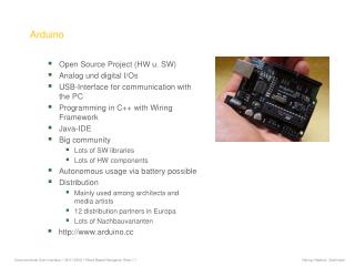
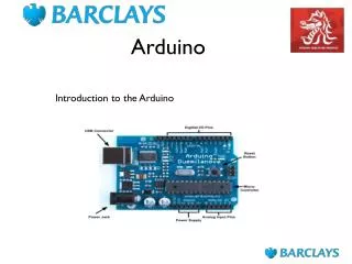
Arduino • An ATmega328 microcontroller wrapped with some convenience circuits • FTDI converts TTL serial to USB • Power regulation, USB overcurrent protection • Standardized form factor means people can build and share daughter boards (“shields”) • Motor shield • Bluetooth, wifi, or GSM shield • Proto shield • LED on pin 13 • Reset button
More Info • General microcontroller explanation from semiconductors and up • http://www.coactionos.com/embedded-design/135-how-microcontrollers-work.html?showall=&limitstart= • Arduino UNO spec page with ATmega328 datasheet: • http://arduino.cc/en/Main/ArduinoBoardUno