Chap. 1
Chap. 1. RISC 32 bit CPU Architecture Introduction. Outline. 1.1 ARM vs. MIPS MIPS Overview ARM Overview 1.2 Samsung S3C2500B (ARM9) Overview Samsung S3C2500B 1.3 IXP (XScale) Overview. MIPS Overview.

Chap. 1
E N D
Presentation Transcript
Chap. 1 RISC 32 bit CPU Architecture Introduction
Outline 1.1 ARM vs. MIPS • MIPS Overview • ARM Overview 1.2 Samsung S3C2500B (ARM9) Overview • Samsung S3C2500B 1.3 IXP (XScale) Overview
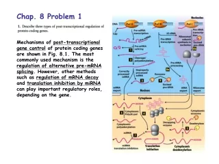
MIPS Overview • The MIPS (Million Instruction Per Second) architecture grew out of research started at Stanford University (Professor John Hennessy). • MIPS project was one of the first publicly known implementations of a Reduced Instruction Set Computer (RISC) architecture. • MIPS processor implemented a smaller, simpler instruction set. • MIPS processor used a technique called pipelining to more efficiently process instructions. • MIPS used 32 registers, each 32 bits wide.
MIPS Instruction Set Overview • MIPS instruction set consists of about 111 total instructions, each represented in 32 bits. • An example of a MIPS instruction is below: • add $r10, $r7, $r8 000000 00111 01000 01010 00000 010100 $r10 $r7 $r8
Outline 1.1 ARM vs. MIPS • MIPS Overview • ARM Overview 1.2 Samsung S3C2500B (ARM9) Overview • Samsung S3C2500B 1.3 IXP (XScale) Overview
ARM Overview • Advances RISC Machines (now known as ARM) was established in November 1990. • ARM (formerly Advanced RISC Machines) • ARM7, ARM9, ARM10, ARM 11 • StrongARM, Xscale (PXA, IXP, IXC, etc.) • The standard way to perform I/O functions on ARM systems is by the use of memory- mapped I/O.
I/O Mapped I/O • 每一個控制器上的暫存器都被給定一個特殊的 I/O 埠。 • Intel 的 IN 跟 OUT 指令可以用來分別讀出或寫入暫存器的值。 CPU AX 控制器 I/O埠 0x68 Outw AX, 0x68 0x15D4 0x15D4
記憶體 0x0000 0xF000 0xFFFF CPU movw 0xF000, BX movw AX, [BX] AX 0x15D4 控制器暫存器 位址0xF000 0x15D4 Memory Mapped I/O • 記憶體對映 I/O 是將週邊設備的暫存器映對到記憶體位址空間。 • CPU 在存取這些暫存器時,就像是在存取記憶體裡面的值一樣。
ARM Overview • ARM is fully 16/32-bit RISC architecture • ARM variants are in widespread use in embedded and Low-power applications due to their power saving design features. • Power consumption: CPU Power W Clock /MHz • ARM7TDMI: < 0.25 60 -110 • ARM7TDMI-S: < 0.4 >50 • ARM9TDMI: 0.3 167 - 220 • ARM1020E: ~0.85 200 - 400 • IXP (XScale): 1.2 533 • Inter 486 cpu: 10 50
ARM Overview • ARM incorporates the following typical RISC architecture features: • A load/store architecture • data-processing operations only operate on register contents, not directly on memory contents. • Simple addressing modes • all load/store addresses being determined from register contents and instruction fields only. • Pipelined • (ARM7: 3 stages) • (ARM7: 5 stages) • Uniform and fixed-length instruction fields, to simplify instruction decode.
ARM Overview • The ARM processor has a total of 37 registers: • 31 general-purpose 32bit registers. • 6 status registers. • 16 general registers and one or two status registers are visible at any time. • The visible registers depend on the processor mode. • The other registers (the banked registers) are switched in to support IRQ, FIQ, Supervisor, Abort and Undefined mode processing.
ARM Overview • Registers: • R0 to R15 are directly accessible. • R0 to R12 are general purpose. • R13 is the Stack Pointer (SP). • R14 is the Link Register (LR). • R15 is the Program Counter (PC).
ARM Overview • Current program status register (CPSR) • CPSR is accessible in all processor modes. • It contains the following condition code: • Flags, interrupt disable bits, the current processor mode, other status and control information. • Saved program status register (SPSR) • SPSR is used to preserve the value of the CPSR when the associated exception occurs.
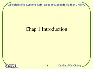
ARM Overview • Register organization in ARM state • Registers are arranged in partially overlapping banks, with a different register bank for each processor mode, as shown in Figure 1. Figure.1
ARM Overview • For detail information about the ARM CPU Architecture and Register organization, we will introduce in Chap 3.
Outline 1.1 ARM vs. MIPS • MIPS Overview • ARM Overview 1.2 Samsung S3C2500B (ARM9) Overview • Samsung S3C2500B 1.3 IXP (XScale) Overview
Product overview • S3C2500B • 16/32-bit RISC • Cost-effective, high-performance microcontroller solution for Ethernet-based system • SOHO router, Internet gateway, WLAN AP, etc. • S3C2500B built an outstanding CPU core • 16/32-bit ARM940TDMI cached processor RISC processor • TDMI means Thumb mode, Debugger core, faster Multiplier, embedded ICE logic • Integrate 4KB instruction/data caches, write buffer, AMBA bus interface
Write policies • write through • 任何時間, 若cache內之資料有被修改, 則亦立即修改主記憶體之相對內容 • buffer write-through: use write buffers to decouple the write operations of the CPU from external bus writing to main memory • write back • 當cpu要須改cache內容時, 僅修改cache • 僅當此slot要被換掉時, 才其內容寫到主記憶體內 • 會有cache coherency 的問題, 即cache內的內容會和主記憶體的內容不同 Cache Processor DRAM Write Buffer
S3C2500B product overview • Integrated the following on-chip functions • ARM940T cached processor • 8k-byte unified cache/SRAM • I2C interface • Ethernet controller • HDLC controller • GDMA controller • UART controller • USB controller • IOM2 controller • Programmable I/O ports • Interrupt Controller
Product Overview - Features • Architectures • Embedded in Circuit emulator (ICE) • Little/big-endian mode supported (Internal architecture is big-endian) • System manager • 8/16/32-bit external bus support for ROM/SRAM, flash memory, DRAM, and external I/O, Support EDO/normal or SDRAM • Four-word depth write buffer • Cost-effective memory-to-peripheral DMA interface • Unified instruction/data cache • Two-way set-associative, unified 8k-byte cache • Support for LRU (least recently used) replacement protocol • I2C serial interface • Ethernet controller (10/100-Mbps full-duplex) • HDLC • DMA controller (2-channel general DMA) • For memory-to-memory, memory-to-UART, UART-to-memory • UARTs (two UART with DMA-based or interrupt-based operation) • Timers (two 32-bit timers with interval mode or toggle mode operation) • Programmable I/O (64 programmable I/O ports) • Interrupt controller (21 interrupt sources, includes 4 external interrupt) • Universal Serial Bus (USB) • USB 1.1 compliant • Full speed 12 Mbps operation
Outline 1.1 ARM vs. MIPS • MIPS Overview • ARM Overview 1.2 S3C4510 (ARM7) Overview • Samsung S3C4510B 1.3 IXP (XScale) Overview
IXP (XScale) Overview • Intel XScale core • Intel StrongARM V5 compliant • 266, 400, and 533 MHz • 3 Network Processor Engines (NPE) • Ethernet filtering • ATM SARing • HDLC
IXP (XScale) Overview (con’t) • USB 1.1 device controller • Full-speed • 16 endpoints • PCI controller • 32-bit interface • PCI Spec. Rev. 1.1 compatible • Host/option capable • Master/target capable • Two DMA channels • 264 MBps peak data rate
IXP (XScale) Overview (con’t) • 2 Ethernet MACs • ADSL support • Hardware security accelerator • DES, 3DES, SHA-1, and MD5 • AES 128-bit and 256-bit • For VPN, Wireless,... Etc. applications • UTOPIA-2 Interface • Low Power consumption • 1.2W @ 533MHz
IXP (XScale) Overview (con’t) • DSP support for: • TI DSPs supporting HPI-8/HPI-16 bus cycles • Internal bus monitoring unit • Seven 27-bit event counters • Monitors internal bus occurrence and duration events • High-speed UART • Expansion bus interface
IXP (XScale) Overview (con’t) • Typical Applications • High performance DSL modem • High performance cable modem • Residential gateway • SME router • Integrated access device (IAD) • Set-top box • DSLAM • Access Points 801.11 a/b/g • Network Printers
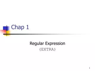
IXP (XScale) Architecture • IXP425 hardware block diagram
IXP (XScale) Architecture • XScale core block diagram
IXP (XScale) Core • Intel StrongARM V5TE compliant • Seven/eight-stage super-pipeline • Integer pipe • Multiply-accumulate (MAC) pipe • Memory pipe • Multiple-accumulate coprocessor • Can do 2 simultaneous, 16 bit, SIMD multiplies with 40-bit accumulation
IXP (XScale) Core (cont’d) • Management unit • 32-entry, data memory management unit • 32-entry, instruction memory management unit • 32-KByte, 32-way, set associative instruction cache • 32-KByte, 32-way, set associative data cache • 2-KByte, 2-way, set associative mini-data cache • 128-entry, Branch Target Buffer • 8-entry write buffer • 4-entry fill and pend buffers • allow “hit-under-miss” operation with data caches • Debug unit • JTAG interface
IXP (XScale) NPE • Network Processor Engine • Dedicated-function • High performance, hardware-multi-threaded • Dedicated instruction/data memory bus • Used to off load networking functions • Additional assist hardware • Hardware security accelerator • CRC, AAL 2, AES, DES, SHA-1, and MD5