Download
1 / 4
40 likes | 57 Vues
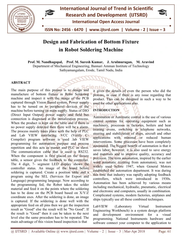
The main purpose of this project is to design and manufacture of bottom fixture in Robo Soldering machine and inspect it with the image of the PCB captured through Vision Based system. Power supply has to be turned on to peripheral devices of the machine before turning on main supply. Status of DIO Direct Input Output power supply and field bus connection is diagnosed at the initialization process. When the product is kept on the table and if there is no power supply detected then there will be a alarm. The process mainly takes place with the help of PLC and Lab VIEW interfacing. VCC Verify C Compiler program software is used .lab VIEW programming for automation purpose and process repetition and this acts as master and PLC as slave. The communication cable that is used is RS232. When the component is first placed on the fixture table, a sensor gives the feedback to the controller. The 4 digit, 7 segment LED display shows the controller status. An image of the board before soldering is captured. Create a position table and a program using the SEL Services for Export and Language programming language. Now according to the programming fed, the Robot takes the solder material and feed it on the points where the soldering has to be done on the PCB board based on X Y Z coordinate axes. After the soldering is done, an image is captured. If the soldering is done well with the appropriate feed on all pins then we get the inspection result as Good else the result will be No Good . If the result is Good then it can be taken to the next level else the same procedure has to be repeated. The main advantage of this vision based inspection is that it gives the details of even the person who did the process, in case if there is any issue regarding that product. This can be designed in such a way to be used for other applications also. Prof. M. Nandhagopal | Prof. M. Suresh Kumar | J. Arulmurugan | M. Aravind "Design and Fabrication of Bottom Fixture in Robot Soldering Machine" Published in International Journal of Trend in Scientific Research and Development (ijtsrd), ISSN: 2456-6470, Volume-2 | Issue-3 , April 2018, URL: https://www.ijtsrd.com/papers/ijtsrd10811.pdf Paper URL: http://www.ijtsrd.com/engineering/mechanical-engineering/10811/design-and-fabrication-of-bottom-fixture-in-robot-soldering-machine/prof-m-nandhagopal<br>

E N D
International Research Research and Development (IJTSRD) International Open Access Journal nd Fabrication of Bottom Fixture n Robot Soldering Machine International Journal of Trend in Scientific Scientific (IJTSRD) International Open Access Journal ISSN No: 2456 ISSN No: 2456 - 6470 | www.ijtsrd.com | Volume 6470 | www.ijtsrd.com | Volume - 2 | Issue – 3 Design and Fabrication in Robot Soldering Machine f Bottom Fixture Prof. M. Nandhagopal, Prof. M. Suresh Kumar, Department of Mechanical Sathyamangalam, Erode Sathyamangalam, Erode, Tamil Nadu, India Prof. M. Suresh Kumar, J. Arulmurugan, Mechanical Engineering, Bannari Amman Institute of Technology Bannari Amman Institute of Technology M. Aravind ABSTRACT The main purpose of this project is to design and manufacture of bottom fixture in Robo Soldering machine and inspect it with the image of the PCB captured through Vision Based system. Power supply has to be turned on to peripheral devices of the machine before turning on main supply. Status of DIO (Direct Input Output) power supply and field bus connection is diagnosed at the initialization process. When the product is kept on the table and if there is no power supply detected then there will be a alarm. The process mainly takes place with the help of PLC and Lab VIEW interfacing. VCC (Verify C Compiler) program software is used .lab VIEW programming for automation purpose an repetition and this acts as master and PLC as slave. The communication cable that is used is RS232. When the component is first placed on the fixture table, a sensor gives the feedback to the controller. The 4 digit, 7- segment LED display shows controller status. An image of the board before soldering is captured. Create a position table and a program using the SEL (Services for Export and Language) programming language. Now according to the programming fed, the Robot takes the solder material and feed it on the points where the soldering has to be done on the PCB board based on X/Y/Z coordinate axes. After the soldering is done, an image is captured. If the soldering is done well with the appropriate feed on all pins then we get the inspectio result as "Good" else the result will be "No Good". If the result is "Good” then it can be taken to the next level else the same procedure has to be repeated. The main advantage of this vision based inspection is that main advantage of this vision based inspection is that The main purpose of this project is to design and manufacture of bottom fixture in Robo Soldering machine and inspect it with the image of the PCB it gives the details of even the per process, in case if there is any issue regarding that product. This can be designed in such a way to be used for other applications also. used for other applications also. it gives the details of even the person who did the process, in case if there is any issue regarding that product. This can be designed in such a way to be ed system. Power supply has to be turned on to peripheral devices of the machine before turning on main supply. Status of DIO (Direct Input Output) power supply and field bus connection is diagnosed at the initialization process. INTRODUCTION Automation or Automatic control is the use of various control systems for operating equipment such as machinery, processes in factories, boilers and heat treating ovens, switching in telephone networks, steering and stabilization of ships, aircraft and other applications with minimal or reduced human interventions. Some processes have been completely automated. The biggest benefit of automation is that it saves labor; however, it is also used to save energy and materials and to improve quality, accuracy and precision. The term automation, inspired by the earlier word automatic (coming from automaton), was not widely used before 1947, when General Motors established the automation department. It was during this time that industry was rapidly adopting feedback controllers, which were introduced in 1930s. Automation has been achieved by various means including mechanical, hydraulic, pneumatic, electrical and electronic and computers, usually in combination. Complicated systems, modern factories, airplanes and ships typically use all these combined techniques. ships typically use all these combined techniques. Automation or Automatic control is the use of various control systems for operating equipment such as rocesses in factories, boilers and heat treating ovens, switching in telephone networks, steering and stabilization of ships, aircraft and other applications with minimal or reduced human interventions. Some processes have been completely ggest benefit of automation is that it saves labor; however, it is also used to save energy and materials and to improve quality, accuracy and precision. The term automation, inspired by the earlier word automatic (coming from automaton), was not ed before 1947, when General Motors established the automation department. It was during this time that industry was rapidly adopting feedback controllers, which were introduced in 1930s. Automation has been achieved by various means hydraulic, pneumatic, electrical and electronic and computers, usually in combination. Complicated systems, modern factories, airplanes and n the table and if there is no power supply detected then there will be a alarm. The process mainly takes place with the help of PLC and Lab VIEW interfacing. VCC (Verify C- Compiler) program software is used .lab VIEW programming for automation purpose and process repetition and this acts as master and PLC as slave. The communication cable that is used is RS232. When the component is first placed on the fixture table, a sensor gives the feedback to the controller. segment LED display shows the controller status. An image of the board before soldering is captured. Create a position table and a program using the SEL (Services for Export and Language) programming language. Now according to the programming fed, the Robot takes the solder l and feed it on the points where the soldering has to be done on the PCB board based on X/Y/Z coordinate axes. After the soldering is done, an image is captured. If the soldering is done well with the appropriate feed on all pins then we get the inspection result as "Good" else the result will be "No Good". If the result is "Good” then it can be taken to the next level else the same procedure has to be repeated. The LabVIEW Engineering Workbench) is a system design platform and development environment programming. National Instruments hardware and software connect your computer to the application to software connect your computer to the application to LabVIEW (Laboratory (Laboratory Virtual Virtual a system design platform environment for Instrument Instrument and programming. National Instruments hardware and development for a a visual visual @ IJTSRD | Available Online @ www.ijtsrd.com @ IJTSRD | Available Online @ www.ijtsrd.com | Volume – 2 | Issue – 3 | Mar-Apr Apr 2018 Page: 61
International Journal of Trend in Scientific Research and Development (IJTSRD) ISSN: 2456 end in Scientific Research and Development (IJTSRD) ISSN: 2456 end in Scientific Research and Development (IJTSRD) ISSN: 2456-6470 offer the widest range of solutions for practically any measurement or automation application. PC based Machine vision system have the flexibility to address the needs of research, test and measurement, and industrial automation vision applications. With this application, any specification can be easily adjusted than with traditional tools. Machine vision system mainly needs camera to acquire the image. mainly needs camera to acquire the image. offer the widest range of solutions for practically any 1. DESIGN tion. PC based Machine vision system have the flexibility to address the needs of research, test and measurement, and industrial automation vision applications. With this application, any specification can be easily adjusted chine vision system The objective of the project is to develop a machine for automatic soldering of PCB (Printed Circuit Board) that is used in DIDs (Driver Information Display) with required amount of solder metal inspect it through Machine Vision system. The system has to integrate mechanical and electronics for a coordinated approach towards making the soldering process automatic. For the soldering to be done without any excess or poor flow, without any formation of solder balls and also without any overlap of solder metal. This design is developed using standard mechanical design components. The design is calculated to be safe and accurate. The objective of the project is to develop a machine for automatic soldering of PCB (Printed Circuit Board) that is used in DIDs (Driver Information Display) with required amount of solder metal and to inspect it through Machine Vision system. The system has to integrate mechanical and electronics for a coordinated approach towards making the soldering process automatic. For the soldering to be done without any excess or poor flow, without any rmation of solder balls and also without any overlap of solder metal. This design is developed using standard mechanical design components. The design is calculated to be safe and Fig 1:Isometric view of overall design Fig 1:Isometric view of overall design DETAILED DRAWING OF COMPONENTS DETAILED DRAWING OF COMPONENTS methods methods of of all all Fixture base plate: The frame is the structural portion which the machine above the table and support it. above the table and support it. The frame is the structural portion which the machine The objective of this project work has been framed and the chapters required for the process development of the Automatic Robot Soldering machine and Vision Based Inspection has been organized. The photographs of the project are included in appendix. The work from the scratch i.e., selection of materials to the fabrication and completion of the project to the fabrication and completion of the project The objective of this project work has been framed and the chapters required for the process development of the Automatic Robot Soldering machine and Vision Based Inspection has been organized. The photographs of the project are included in appendix. The work from the scratch i.e., selection of materials PROBLEM IDENTIFICATION In the robot soldering machine to develop a machine for automatic soldering of PCB (Printed Circuit Board) in the machine there is no proper fixture to hold the PCB in the robot soldering machine. Where there is a poor flow of soldering while the PCB and connector is soldering. The fixture is not available for the all dimensions of various PCB in the robot soldering machine. The fixture is arranged and it is designed for various dimensions of PCB and then the soldering to be done without any excess or poor flow, without any formation of solder balls and also without any overlap of solder metal. This design is developed using standard mechanical design methods of all components. The design is calculated to be safe and accurate. to develop a machine for automatic soldering of PCB (Printed Circuit Board) in the machine there is no proper fixture to ring machine. Where there is a poor flow of soldering while the PCB and connector is soldering. The fixture is not available for the all dimensions of various PCB in the robot soldering machine. The fixture is arranged and it is ions of PCB and then the Push rod: The Push rod is placed above the fixture base plate. The push rod is used to support the PCB while the soldering process takes in the printer circuit board. The robo soldering machine is applied the soldering paste to the PCB with connectors the board will act deform and it may causes damage in the PCB so the push rod is used to support the PCB in the fixture. push rod is used to support the PCB in the fixture. soldering to be done without any excess or poor flow, without any formation of solder balls and also without any overlap of solder metal. This design is developed using standard mechanical design methods of all gn is calculated to be safe and od is placed above the fixture base plate. The push rod is used to support the PCB while the soldering process takes in the printer circuit board. The robo soldering machine is applied the soldering paste to the PCB with connectors the board will act m and it may causes damage in the PCB so the @ IJTSRD | Available Online @ www.ijtsrd.com @ IJTSRD | Available Online @ www.ijtsrd.com | Volume – 2 | Issue – 3 | Mar-Apr Apr 2018 Page: 62
International Journal of Trend in Scientific Research and Development (IJTSRD) ISSN: 2456 end in Scientific Research and Development (IJTSRD) ISSN: 2456 end in Scientific Research and Development (IJTSRD) ISSN: 2456-6470 PCB Side Support: The PCB side support is placed above the fixture base plate. The side support is used to carry the PCB in the fixture plate for the soldering process of connector and printer circuit board. Hinge: The hinge is placed with the hinge support in the machine. The hinge is fixed with the top plate of fixture and hinge support for the opening and closing of top plate of fixture. The PCB side support is placed above the fixture base plate. The side support is used to carry the PCB in the the soldering process of connector placed with the hinge support in the machine. The hinge is fixed with the top plate of fixture and hinge support for the opening and closing Hinge support: The hinge support is placed above the fixture base plate. The hinge support is carry the hinge to support the top plate of the fixture in the machine The hinge support is placed above the fixture base plate. The hinge support is carry the hinge to support the top plate of the fixture in the machine. OPERATION The Printer Circuit Board is placed on the fixture. The and it is designed to hold the Printer Circuit Board in the robo soldering machine. The top plate of the fixture is closed after the board is placed in the fixture. Then the soldering machine is ON and the base plate of fixture is moved to the The Printer Circuit Board is placed on the fixture. The fixture is arranged and it is designed to hold the Printer Circuit Board in the robo soldering machine. The top plate of the fixture is closed after the board is placed in the fixture. Then the soldering machine is ON and the base plate of fixture is moved to the machine for soldering work. The robo is started to soldering work. The robo is started to @ IJTSRD | Available Online @ www.ijtsrd.com @ IJTSRD | Available Online @ www.ijtsrd.com | Volume – 2 | Issue – 3 | Mar-Apr Apr 2018 Page: 63
International Journal of Trend in Scientific Research and Development (IJTSRD) ISSN: 2456-6470 soldering the printer circuit board with connector and LED. After completing the soldering work in the machining process the base plate of the fixture is moved out to the original position then the top plate of fixture is open and the solder printer circuit board with connecters and LED is removed from the fixture. References 1)H Jia, YL Murphey, J Shi, T Chang (2004) "An Intelligent Real-time Vision System for Surface Defect Detection" (IEEE-Proceedings of the 17th International Conference on Pattern Recognition, ) 2)J.O. Park, J. Spingler (2008) "Consideration on the productivity and flexibility in Automatic Soldering using Industrial Robots" International Journal of advanced Robotics, Vol.4, No.7, p, 750-820. ADVANTAGE It reduces labour power Required less time Eye protection due to automation. It protects PCB board during soldering process. Joint soldering should be avoided. More accuracy compare to manual CONCLUSION 3)Lee, C.S., Park,J.O.,(1988)"Development of mechatronics and robot technology", MOST report (2U46-3355-2) 4)N.S.S.Mar, C.Fookes, P.K.D.V Yarlagadda (2001), “Design of Automatic Vision - based inspection system segmentation", IEEE Transactions, Vol.22, No.3. Thus the simultaneous soldering of the accurate position where the soldering has to be done proves not only efficient but also ensures accurate and also customer's requirement can be met easily. Accuracy mainly comes from the inspection that is done after the soldering. Thus the objective of the project to develop an bottom fixture to hold the PCB in Robo Soldering machine is achieved. for solder joint 5)Nam, D.H., Chung, S.J., Yun, G.Y., (1989)"A study on the development of the robotonomic soldering system with vibration method" Second edition, Korea. 6)Petruzella, Frank D. (2005) "Programmable Logic Controllers", States. McGraw-Hill, United 7)Stenerson, John (2002) "Industrial Automation and Process Control", Prentice Hall, First edition, United States. @ IJTSRD | Available Online @ www.ijtsrd.com | Volume – 2 | Issue – 3 | Mar-Apr 2018 Page: 64