Download

1 / 9
90 likes | 105 Vues
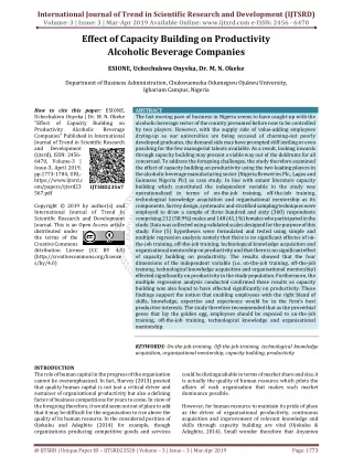
In recent years, tsunami surges several regions in Indonesia, particularly in Sumatera Island which cause the damage to various facilities and infrastructures, even inflicting considerable casualties. The last strong undersea earthquake in Mentawai, West Sumatera on 2009, has warned the government to face the tsunami disaster in next big earthquake. Therefore, it is needed rescue strategies mitigation in the form of vertical evacuation in high and strong buildings, one of which is in the form of providing shelter at vulnerable area to tsunami. Padang City has built a five story shelter building made of Reinforced Concrete Structures located in Ulak Karang, North Padang. Based on the review, there is no tsunami loads consider by the design consultant in designing the shelter due to there is no Indonesian standard code in designing the shelter building. Actually, the tsunami loads should be considered if the shelter will be used for evacuation due to earthquake and tsunami. This paper presents the effect of tsunami loads on Ulak Karang Shelter structure. The comparison of structural responses on the shelter structure with and without impacted by tsunami loads based on FEMA 646 standard code was also discussed. Fauzan | Febrin Anas Ismail | Annisa El Husna | Zev Al Jauhari | Silvia "Effect of Tsunami Loads on Ulak Karang Shelter Building in Padang City" Published in International Journal of Trend in Scientific Research and Development (ijtsrd), ISSN: 2456-6470, Special Issue | International Conference on Advanced Engineering and Information Technology , November 2018, URL: https://www.ijtsrd.com/papers/ijtsrd19130.pdf Paper URL: https://www.ijtsrd.com/engineering/civil-engineering/19130/effect-of-tsunami-loads-on-ulak-karang-shelter-building-in-padang-city/fauzan<br>

E N D
International Journal of Trend in Scientific Research and International Conference on Advanced Engineering and Information Technology (ICAEIT-2017) Effect of Tsunami Loads on Ulak Karang Shelter Building in Padang City International Journal of Trend in Scientific Research and Development (IJTSRD) International Conference on Advanced Engineering and Information Technology (ICAEIT ISSN No: 2456 - 6470 | www.ijtsrd.com | Special Issue Publication International Conference on Advanced Engineering ISSN No: 2456 Special Issue Publication Effect of Tsuna Shelter Fauzan, Febrin Anas Ismail, Annisa El Husna, Zev Al Department of Civil Engineering, Engineering Faculty, Andalas University, Indonesia f Civil Engineering, Engineering Faculty, Andalas University, Indonesia f Civil Engineering, Engineering Faculty, Andalas University, Indonesia mi Loads on Ulak Karang Fauzan, Febrin Anas Ismail, Annisa El Husna, Zev Al Jauhari, Silvia Jauhari, Silvia ABSTRACT In recent years, tsunami surges several regions in Indonesia, particularly in Sumatera cause the damage to various facilities infrastructures, even inflicting considerable casualties. The last strong undersea earthquake in Mentawai, West Sumatera on 2009, has warned the government to face the tsunami disaster in next big ear Therefore, it is needed rescue strategies (mitigation) in the form of vertical evacuation in high and strong buildings, one of which is in the form of providing shelter at vulnerable area to tsunami. Padang City has built a five-story shelter building made of Reinforced Concrete Structures located in Ulak Karang, North Padang. Based on the review, there is no tsunami loads consider by the design consultant in designing the shelter due to there is no Indonesian standard code in designing the shelter building. Actually, the tsunami loads should be considered if the shelter will be used for evacuation due to earthquake and tsunami. This paper presents the effect of tsunami loads on Ulak Karang Shelter structure. The comparison of structural responses on the shelter structure with and without impacted by tsunami loads based on FEMA 646 standard code was also discussed. Keywords: Tsunami loads, earthquake, internal forces, load-bearing capacity, shelter, FEMA P 1.INTRODUCTION West Sumatra province, especially in Padang City, is an area that prone to earthquake and tsunami because it was loacated in the two plate adjacent (Indian and Asian coastline). Earthquake in West Sumatra is kind of strong earthquakes that could lead to tsunami. In addition to vulnerable areas, population tsunami. In addition to vulnerable areas, population density distribution of Padang Therefore, when the tsunami happens, population of the city would be difficult to be evacuated horizontally, experiencing traffic congestion due to the unsufficient road infrastructure in Padang City. Therefore, it is necessary to evacuate vertically in and strong buildings to minimize the risk of casualties during the tsunami. One of them is establishing the provision of Temporary Evacuation Sites (TES) around areas that prone of tsunami, which can protect the people living in the area of the tsunami affected areas are generally located close to the source of the earthquake, the TES building must also meet the requirements of earthquake Therefore, the government of Padang City takes action to plan a TES namely Ulak Karang Shelter, in North Padang (Fig. 1), to evacuation when a big earthquake occurs followed by tsunami. Thus, in designing a shelter building, it must be pay attention and detail to input the working loads in the building such as dead, live, earthquake, and tsunami loads. In recent years, tsunami surges several regions in Indonesia, particularly in Sumatera Island which Padang is very alarming. Therefore, when the tsunami happens, population of the city would be difficult to be evacuated horizontally, experiencing traffic congestion due to the unsufficient road infrastructure in Padang City. facilities and considerable casualties. strong undersea earthquake in Mentawai, West Sumatera on 2009, has warned the government to face the tsunami disaster in next big earthquake. Therefore, it is needed rescue strategies (mitigation) in the form of vertical evacuation in high and strong buildings, one of which is in the form of providing shelter at vulnerable area to tsunami. Padang City has evacuate vertically in tall strong buildings to minimize the risk of casualties One of them is establishing the provision of Temporary Evacuation Sites (TES) around areas that prone of tsunami, which can protect the people living in the area of the tsunami disaster. Because the affected areas are generally located close to the source of the earthquake, the TES building must also meet the requirements of earthquake-resistant buildings. ding made of Reinforced Concrete Structures located in Ulak Karang, North Padang. Based on the review, there is no tsunami loads consider by the design consultant in designing the shelter due to there is no Indonesian standard code building. Actually, the tsunami loads should be considered if the shelter will be used for evacuation due to earthquake and tsunami. This paper presents the effect of tsunami loads on Ulak Karang Shelter structure. The comparison of n the shelter structure with and without impacted by tsunami loads based on FEMA- Therefore, the government of Padang City takes ly Ulak Karang Shelter, in be used as a vertical evacuation when a big earthquake occurs followed by tsunami. Thus, in designing a shelter building, it must be pay attention and detail to input the working loads ch as dead, live, earthquake, and Tsunami loads, earthquake, internal bearing capacity, shelter, FEMA P-646 West Sumatra province, especially in Padang City, is an area that prone to earthquake and tsunami because it was loacated in the two plate adjacent (Indian and West Sumatra is a of strong earthquakes that could lead to a (a) Front view (a) Front view @ IJTSRD | Available Online @ www.ijtsrd.com | Special Issue Publication | November 2018 @ IJTSRD | Available Online @ www.ijtsrd.com | Special Issue Publication | November 2018 @ IJTSRD | Available Online @ www.ijtsrd.com | Special Issue Publication | November 2018 P - 165
International Journal of Trend in Scientific Research and Development (IJTSRD) | ISSN: 2456-647 29,05 MPa) and yield strength of reinforcement (fy) was 400 MPa. All working loads are taken into account including the dead load / weight of its own building, live load, seismic (earthquake) load, and tsunami loads. 2.1. Design of loads The standard code of the minimum load for design of buildings and other structures, SNI 1727-2013 [4], was used to design the loads of the building. The working loads include live load, dead load and seismic load. The dead load includes all components of the building structure, namely beams, columns, plates, and load-bearing walls. Live load used was 250 kg/m2, where the function of the building is as office and evacuation building. 2.2. Earthquake Response Spectrum Seismic load based on SNI 1726-2012 using response spectrum was obtained http://puskim.pu.go.id/Aplikasi/desain_spektra_indon esi a_2011/ by entering the name of city. Figure 3 shows the response spectrum of Padang City with soft soil type. The value of spectral design SD1 and SDS are 0,6g and 0,932g, respectively [5]. (b) 3D view Figure1. Front and 3D view of Ulak Karang Shelter Building [2] However, the design consultant did not consider the tsunami loads in designing the structure of the Ulak Karang Shelter due to there is no standard code in Indonesia for designing the tsunami shelter. Therefore, the structures of Ulak karang shelter should be evaluated before using as a vertical evacuation building due to tsunami disaster. In this study, the Ulak Karang Shelter was evaluated based on FEMA-646 standard code [1]. from the website Figure2. Location of shelter [Google Earth] 2.Structural analysis Feasibility evaluation of the structure consists of serviceability limit performance performance ultimate limit that determined by the story drift, the axial and bending moment capacity of the column using the column P -M interaction diagram, and the load-bearing capacity of beam [3]. The Ulak Karang Shelter located in Padang City, with position at ± 700 m from the beach of Padang (Fig. 2). The building is five- story reinforced concrete frame structure. The structure consists of columns, beams and slabs. The shape of the building is rectangular with area of 672 m2. Ulak Karang Shelter Building has height of 20,65 m excluding the roof, number of columns each floor is 56, with two different sizes, dimensions: D-60 cm and 60 cm x 40 cm. Each column is associated with three types of beam size with dimensions: 40 cm x 60 cm, 40 cm x 50 cm, and 30 cm x 30 cm. Concrete strength was K-350 (fc'= evaluation, Figure3. Earthquake response Spectrum design of Padang City [5] 2.3. Tsunami loads Tsunami loads are calculated based on the FEMA P- 646 Code, which is published on April 2012. 2.3.1. Hydrostatic Force Hydrostatic force is the horizontal force that caused by the water pressure against to a surface. The amount of this force depends on the depth of water [1]. Hydrostatic force can be calculated by the equation: @ IJTSRD | Available Online @ www.ijtsrd.com | Special Issue Publication | November 2018 P - 166
International Journal of Trend in Scientific Research and Development (IJTSRD) | ISSN: 2456-647 Where: Fh is hydrostatic force, pc is hydrostatic pressure at the central of the wetted, portion of the wall panel, Aw is the wetted area of the panel, ρs is weight/ volume of tsunami (1100 kg/m3), g is acceleration of gravity, b is width that accept the pressure, hmax is the maximum of water height above the wall base, R* is the maximum run up elevation of tsunami, zw is the height of wall panel, These loads are given by equal triangles on tsunami submerged area, as seen in the Fig. 4. Figure5. The acting of buoyant force on the structure of Ulak Karang Shelter 2.3.3. Hydrodinamic Force Hydrodynamic force is a combination of horizontal forces caused by the compressive force of moving water and the friction caused by the flow around the structure [1]. Hydrodynamic force can be calculated by the equation Figure4. Distribution of hydrostatic load [1] 2.3.2. Bouyant Force The buoyant forces on a structure subject to partial or total submergence will act vertically through the center of mass of the displaced volume. Buoyant forces are a concern for wood frame buildings, empty above-ground and below-ground tanks. For evaluation of an individual floor panel where the water level outside differs substantially from the level inside [1]. The buoyant force on the structure can be calculated by the equation: where: Fd is hydrodynamic force Cd is the drag coefficient = 2 B is the width of structure h is the depth of flow u is the flow velocity Hydrodynamic force is distributed load on the heigth of column affected tsunami flow, as seen in the Figure 6. where: Fb is the bouyant force, V is the volume of water below the maximum inundation. The buoyant force was distributed load on the top floor that flooded by the tsunami, as seen in the Figure 5. @ IJTSRD | Available Online @ www.ijtsrd.com | Special Issue Publication | November 2018 P - 167
International Journal of Trend in Scientific Research and Development (IJTSRD) | ISSN: 2456-647 The impact force is distributed load to the structural elements that affected the first part of the tsunami flow, as seen in the Figure 8. Figure6. Distribution of hydrodynamic load on the structure of Ulak Karang Shelter 2.3.4. Surge Force (Impulse Force) Surge forces are caused by the leading edge of a surge of water impinging on a structure and by the water wave that comes suddenly. Surge force of the building is 1.5 times the hydrodynamic force (Fig. 7). Figure8. Impact load on the structure of Ulak Karang Shelter 2.3.6. Debris load Debris impact is caused by a buildup of debris that assumed by additional hydrodynamic force and depends on the thickness of the layer of debris. To calculate the debris force, use the equation: Figure7. Surge force on the structure of Ulak Karang Shelter where: Fdm is debris force Bd is breadth 2.3.7. Extra gravity load Water suspended above the floor will be an additional load of gravity before the entire pool of back retroactively. The depth of stagnant water depending on the maximum height and horizontal forces flooded walls. Due to the high depreciation rate of water is rapid, it is likely that there will plenty of water suspended in the floor, causing the addition of a significant gravitational force on the floor (Fig. 9). Potential extra load of gravity per unit area can be calculated by the equation: 2.3.5. Impact load Impact loads are those that result from debris such as driftwood, small boats, portions of house, or any object transported by floodwaters, striking against buildings and structures. The influence of the mass of debris that swept by water can be a major cause of building damage. The force is difficult to establish accurate values. As an approach, this value is calculated by the following equation: where: Fi is impact force umax is the maximum flow k is the stiffness of debris mass md is the mass of debris c is hydrodinamic coefficient where: fr is extra gravity load @ IJTSRD | Available Online @ www.ijtsrd.com | Special Issue Publication | November 2018 P - 168
International Journal of Trend in Scientific Research and Development (IJTSRD) | ISSN: 2456-647 hr is the maximum depth of water suspended in the floor hmax is expected maximum height of inundation hl is the maximum height of inundation predicted hbw is the maximum depth of water suspended prior to wall failure due to hydrostatic force Figure11. Plan puddle of tsunami Table 1: Type and value of tsunami loads on the structure of Ulak Karang Shelter Code Type of Tsunami Load Value of Force Fh *Hydrostatic Fb Bouyant Fd Hydrodinamic Fs Surge/ Impulse Fi Impact Fdm Debris Fu Uplift of Hydrodinamic Fr Extra Gravity 1279.3 kg 1815 kg 3251 kg 4876.49 kg 47643.17 kg 3251 kg 0.37 kg/m2 1978.35 kg/m2 Figure9. Extra gravity load on the structure of Ulak Karang Shelter 2.3.8. Uplift hydrodinamic load Uplift hydrodynamic force is given on the top floor of the tsunami inundation affected, as shown in Fig. 10. This load can be calculated by the equation: 2.3. The Importance of building factor (Ie), reduction seismic factor (R), and redudancy factor (ρ) Based on SNI 1726-2012, the shelter building has earthquake risk category of IV with the Importance of the Building Factor (Ie) = 1.5. Reduction Seismic Factor (R) is 6.0 for the evacuation and office building (reinforced concrete building). For the planned structure with seismic design category D, the redundancy value (ρ) is 1.3. 2.4. Combination of loads Combination of loads in SNI 1726-2012 (Earthquake code) was used, which was combined with the combination of tsunami loads based on FEMA P-646: 1.1,2D + 1Fd + 1Fs + 1Fb + 1Fu + 1 LREF + 0,25 L 2.1,2D + 1Fi + 1Fd + 1Fb + 1Fu + 1 LREF + 0,25 L 3.1,2D + 1Fd + 1Fdm + 1Fb + 1Fu + 1 LREF + 0,25 L 4.1,2D + 1Fr + 1Fb + 1Fu + 1 LREF + 0,25 L 5.0,9D + 1Fd + 1Fs + 1Fb + 1Fu 6.0,9D + 1Fi + 1Fd + 1Fb + 1Fu 7.0,9D + 1Fd + 1Fdm + 1Fb + 1Fu 8.0,9D + 1Fr + 1Fb + 1Fu where: D = Dead Load L = Life Load LREF = Life Refugee Load Fi = Impact Load Figure10. Uplift hydrodinamic load on the structure of Ulak Karang Shelter The value of each loads were calculated based on the predictions of tsunami gradeelevation, distance from the waterfront, and other assumptions, as seen in the Fig. 11. The calculation results of tsunami loads is given in Table 1. Elevation shelter that inundation is calculated based on the standard FEMA 646, as follows: 1.Data Map Tsunami Plan and Google Earth 2.Elevation basic structure (Google Earth) (Z) = 3 mdpl 3.Run-up (Tsunami Hazard Maps) (R*) = 7 mdpl 4.Run-up Design (R) = 9.1 mdpl 5.Maximum Depth of Puddle (hmax) = 6.1 m height, shelter sub safe from tsunami 8. @ IJTSRD | Available Online @ www.ijtsrd.com | Special Issue Publication | November 2018 P - 169
International Journal of Trend in Scientific Research and Development (IJTSRD) | ISSN: 2456-647 Fdm = Debris Dam Load Fd = Hydrodynamic Load Fs = Impulsive Load Fb = Buoyant Load Fu = Uplift Load 2.5. Modeling of Structure The building is modeled into 3D and then analyzed by using structural analysis program, ETABS v9.7.1 [7]. Columns and beams are modeled as an element of the frame, while the slabs are modeled as shell element. Modeling of the building structure is performed in accordance with the drawing of the design consultant. Figure 12 shows the structural modeling of Ulak Karang Shelter Building. respectively. These values are less than the allowable inter story drift of 0.0519 m, so it means that the Ulak Karang Shelter building structure is capable of resisting the working loads. Table 2: Interstory drift of structure without tsunami loads Story 1 5.43 5.43 2 13.18 7.75 3 18.95 5.77 4 22.62 3.67 5 24.52 1.9 Disp. (mm) (mm) 1 10.93 10.93 2 24.1 13.17 3 26.15 2.05 4 29.85 3.7 5 32.29 2.44 Table 3: Interstory drift of structure with tsunami loads Story 1 5.5 5.5 2 13.18 7.68 3 18.95 5.77 4 22.55 3.6 5 24.59 2.04 Story 1 10.83 10.83 2 24.2 13.37 3 26.05 1.85 4 29.85 3.8 5 32.29 2.44 3.2. Internal Force of Columns and Beams Table 4 show the results of internal forces on columns with and without tsunami loads. It can be seen from the table that the internal forces on interior column with tsunami loads calculated based on FEMA P-646 was higher than those calculated without tsunami loads. The values of axial, shear and bending moment Disp. (mm) Drift X (mm) Δs Δa (mm) Δs ≤ Δa (mm) 19.910 51.346 OK 28.417 51.923 OK 21.157 51.923 OK 13.457 46.154 OK 6.967 36.923 OK DriftY Δs Δa (mm) 51.346 51.923 51.923 Δs ≤ Δa OK OK OK OK OK Story (mm) 40.08 48.29 7.517 13.567 46.154 8.947 36.923 Figure12. 3-D Modelling of Ulak Karang Shelter Structure Disp. (mm) Drift X (mm) Δs Δa (mm) Δs ≤ Δa 3. Result and discussion 3.1. Inter story drift Based on SNI 1726-2012, the inter story drift (Δ) must be calculated as using the following equation: (mm) 20.167 51.346 OK 28.160 51.923 OK 21.157 51.923 OK 13.200 46.154 OK 7.480 36.923 OK Disp. (mm) Drift Y (mm) Δs Δa (mm) Δs ≤ Δa where: Δ = Inter story drift Δa = Inter story drift allowable Cd = Enlargement deflection factor Ie = Importance of the building factor h = Height of each floor δ = Difference of story drift ρ = Redundancies factor Tables 2 and 3 show the inter story drift value of building structure analyzed by using SNI 03-1726- 2012 and FEMA in x and y-directions, respectively. From the tables, it can be seen that the maximum of story drift for x and y-direction of structure with tsunami loads are 0.0281 m and 0.0490 m, (mm) 39.710 51.346 OK 49.023 51.923 OK 6.783 51.923 OK 13.933 46.154 OK 8.947 36.923 OK @ IJTSRD | Available Online @ www.ijtsrd.com | Special Issue Publication | November 2018 P - 170
International Journal of Trend in Scientific Research and Development (IJTSRD) | ISSN: 2456-647 of the columns increase byaround 5-27%, 9-49%, and 18-49%, respectively. The internal forces on the beams show similar tendency with the column results. As seen in Tables 5, the shear and bending moment of the beam with tsunami loads using FEMA P-646 was increase by around 7-39% and 8-45%, respectively. The higher of the internal forces especially occurs in the columns of the 1st floor and in the beams on the 2nd floor. Table 4: Internal Force of Columns Without Tsunami Load P(kN) V(kN) M(kNm) P(kN) V(kN) M(kNm) C -2257 -133 -208 T 709 128 212 C -1725 -93 -170 T 235 104 181 C -1042 -46 -166 T 174 176 173 C -1364 -268 -159 T 0.6 260 146 With Tsunami Load Different (%) P V 12.1 30.3 0.0 39.6 0.3 30.0 49.1 15.4 13.2 93.0 33.8 0.0 260.8 64.4 106.4 99.8 59.5 Column M 35.6 26.3 18.2 14.6 49.6 0.0 -2570 709 -1719 462 -920 263 -378 379 -191 212 -133 123 -663 176 -163 163 -323 288 -208 212 -330 173 -77 94 K1 (Ø60) Exterior K1 (Ø60) Interior K1 (60.40) Exterior K1 (60.40) Exterior 55.3 Table 5: Internal Force of Beams Without Tsunami Load With Tsunami Load Different (%) V(kN) M(kNm) V(kN) -257 -277 -191 261 176 212 -228 -271 -319 184 256 184 -68 -70 -17 51.9 61.5 17.38 3.2. Load-bearing capacity of Structure Load-bearing capacity of the structure building, such as columns and beams, were calculated through P-M interaction diagram and shear capacity for columns, and the flexural and shear capacities for beams. 3.2.1. Load-bearing Capacity of Columns P-M Interaction diagram is a diagram that illustrates the ability or capacity of the column is based on the relationship between the bending moment and axial loads in column. Figures 13 and 14 show the interaction P-M diagram obtained from structural analysis results of the shelter building with and without tsunami loads, respectively. Column M(kNm) -323 288 -349 329 -20 18.15 V M 16.8 63.0 28.9 28.2 71.5 70.5 C T C T C T 34.4 18.5 40.2 0.05 74.2 66.5 BA1 (40x60) 2nd Floor BB1 (40x50) 2nd Floor BC1 (30x30) 2nd Floor (b) K1 (Ø60cm) at 1st floor (Exterior) (c) K2 (60x40 cm) at 1st floor (Interior) (a) K1 (Ø60cm) at 1st floor (Interior) @ IJTSRD | Available Online @ www.ijtsrd.com | Special Issue Publication | November 2018 P - 171
International Journal of Trend in Scientific Research and Development (IJTSRD) | ISSN: 2456-647 (d) K2 (60x40 cm) at 1st floor (Exterior) Figure13. Interaction P-M diagram of column without tsunami loads Based on the P-M diagram of column in the structures impacted tsunami loads (Fig. 15), it appears that the axials and moments of the columns on the 1st floor were outside the interaction diagram. This indicates that the columns are not strong enough to resist the working loads including tsunami loads. The column should be retrofitted if the shelter still use as a vertical evacuation building for tsunami. (d) K2 (60x40 cm) at 1st floor (Exterior) Figure14. Interaction P-M diagram of column with tsunami loads 3.2.2. Load-bearing Capacity of Beams Tables 6 to 9 show the flexural and shear capacity of the beam with and without tsunami loads. From Table 7, it can be seen that the flexural capacity of beams in 2nd floor are not strong enough to resist the working loads. This means the beam should be strengthened. Meanwhile, the shear capacity of the beams is strong enough and able to withstand the working loads (Table 9). Table 6: Flexure Capacity of Beam without Tsunami Loads Num. of Bar ΦMn (kN) Tens. Com. BA1 40/60 4D22 2D22 265 BB1 40/50 4D22 2D22 271 BC1 30/30 4D22 4D22 119 Table 7: Flexure Capacity of Beam with Tsunami Loads Num. of Bar ΦMn (kN) Tens. Com. BA1 40/60 4D22 2D22 265 BB1 40/50 4D22 2D22 271 BC1 30/30 4D22 4D22 119 Note Mu (kN) 277 176 271 256 70 61 Beam M u ≤ Mn P M P M P M 6D22 3D22 395 OK OK OK NOT OK OK (a) K1 (Ø60cm) at 1st floor (Interior) 6D22 3D22 322 4D22 4D22 119 Note Mu (kN) 323 288 349 329 20 18 Beam (b) K1 (Ø60cm) at 1st floor (Exterior) M u ≤ Mn P M P M P M 6D22 3D22 395 OK NOT NOT NOT OK OK 6D22 3D22 322 4D22 4D22 119 (c) K2 (60x40 cm) at 1st floor (Interior) @ IJTSRD | Available Online @ www.ijtsrd.com | Special Issue Publication | November 2018 P - 172
International Journal of Trend in Scientific Research and Development (IJTSRD) | ISSN: 2456-647 Table 8: Shear Capacity of Beam with Tsunami Loads Beam ΦVn (kN) (kN) BA1 40/60 335 261 BB1 40/50 276 184 BC1 30/30 315 51 Table 9: Shear Capacity of Beam with Tsunami Beam ΦVn (kN) (kN) BA1 40/60 335 212 BB1 40/50 276 184 BC1 30/30 315 17 4.Conclusion The addition tsunami loads on the shelter building affect load-bearing capacity of shelter structure. The capacity of columns on 1st floor and beams on the 2nd floor are not strong enough to resist the working loads. Tsunami loads on the structure building increase the column internal forces by around 5-27%, 9-49%, and 18-49%, for axial, shear and bending moment respectively. Similarly, the beam internal forces increase by around 7-39% and 8-45%, for shear and bending moment respectively. The higher of the forces especially occurs in the columns of the 1st floor and in the beams on the 2nd floor. The Ulak Karang shelter should be retrofitted before it is used as a vertical evacuation building for tsunami. 5.References 1.FEMA P-646, 2012, Guidelines for Design of Structures for Vertical Evacuation from Tsunamis Applied Technology Council, Redwood City California Note Vu M u ≤ Mn P M P M P M 514 257 OK OK OK OK OK OK 424 228 315 68 2.Natawidjaja, D., H., K., and J., Suprijanto, 1995 Gempa Bumi Tektonik, In Annual Convention of Geoteknologi : LIPI. Note Vu M u ≤ Mn P M P M P M 3.Natawidjaja, D., H., 2002, Ph., D Thesis, Institute of Technology : California. 514 191 OK OK OK OK OK OK 4.Nazwil, 2007, Wilayah Rawan Tsunami, Skripsi Departemen Geografi FMIPA UI, Jakarta. 424 319 315 17 5.SNI 2847-2013, “Persyaratan Beton Struktural Untuk Bangunan Gedung”. 6.SNI 03-1726-2002, “Tata Cara Perencanaan Ketahanan Gempa Untuk Bangunan Gedung”, Indonesia. 7.SNI Ketahanan Gempa Untuk Bangunan Gedung dan Non Gedung”, Indonesia. 1726-2012, “Tata Cara Perencanaan 8.Yudhicara, 2008, Kaitan Antara Karakteristik Pantai Provinsi Sumatera Barat Dengan Potensi Kerawanan Tsunami, Pusat Vulkanologi Dan Mitigasi Bencana Geologi: Bandung. 9.Lambourne, H., (March 2005), “Tsunami: Anatomy of a Disaster”, BBC News, Link: http://news.bbc.co.uk/2/hi/science/nature/4381395 . stm. @ IJTSRD | Available Online @ www.ijtsrd.com | Special Issue Publication | November 2018 P - 173