Download
1 / 4
40 likes | 162 Vues
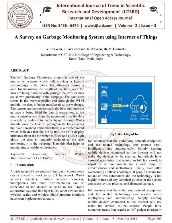
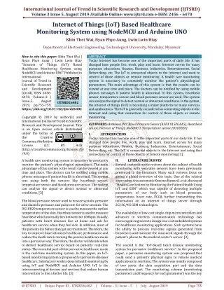
In last few years there is a rapid growth in urbandevelopment plans, the concept of smart cities.While the thought comes up for Smart cities there is a requirement for Smart waste management. The idea of Garbage monitoring system is for the Smart buildings, Colleges, Hospitals and Bus stands. The Garbage monitoring system thought is an improvement of normal dustbin by elevating it to be smart using sensors. Garbage monitoring system is a new idea of implementation which makes a normal dustbin smart using ultrasonic sensors for garbage level detection, display and sending message to the concern department person updating the status of the bin using GSM modem. P. Ramchandar Rao | S. Sanjay Kumar | Ch. Rajendra Prasad "Garbage Monitoring System using Arduino" Published in International Journal of Trend in Scientific Research and Development (ijtsrd), ISSN: 2456-6470, Volume-1 | Issue-6 , October 2017, URL: https://www.ijtsrd.com/papers/ijtsrd4602.pdf Paper URL: http://www.ijtsrd.com/engineering/electronics-and-communication-engineering/4602/garbage-monitoring-system-using-arduino/p-ramchandar-rao<br>

E N D
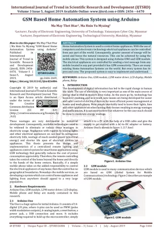
International Journal of Trend in Scientific Research and Development (IJTSRD) International Open Access Journal ISSN No: 2456 - 6470 | www.ijtsrd.com | Volume - 1 | Issue – 6 Garbage Monitoring System using Arduino P. Ramchandar Rao Assistant Professor, Department of ECE, SR Engineering College, Warngal, Telangana S. Sanjay Kumar Assistant Professor, Department of ECE, SR Engineering College, Warngal, Telangana Ch. Rajendra Prasad Assistant Professor, Department of ECE, SR Engineering College, Warngal, Telangana ABSTRACT In last few years there is a rapid growth in urban development plans, the concept of smart cities. While the thought comes up for Smart cities there is a requirement for Smart waste management. The idea of Garbage monitoring system is for the Smart buildings, Colleges, Hospitals and Bus stands. The Garbage monitoring system thought is an improvement of normal dustbin by elevating it to be smart using sensors. Garbage monitoring system is a new idea of implementation which makes a normal dustbin smart using ultrasonic sensors for garbage level detection, display and sending message to the concern department person updating the status of the bin using GSM modem. Keywords:Ultrasonic sensor, Liquid Crystal Display, Arduino Board, Global communication (GSM) INTRODUCTION: Garbage! In our daily life, we see the pictures of garbage bins being overfull and all the garbage smells out. This leads to the number of diseases as large number of insects and mosquitoes breed on it. A big face up to the smart cities is solid waste management, not only in India almost all the countries in the world. This project gives the most efficient ways to keep our environment clean and green. The upcoming large number of smart cities, responsibilities is also required to be fulfilled. The most important need of a smart way of life begins with cleanliness and cleanliness begins with smart dustbin. A people will get its waste dispatch properly only if the dustbins are placed well and collected well. The main problem in the current waste management system in most of the cities is the damaging status of dustbins. So, by using the new technology we send the information to the concern persons and display boards are arranged in the concern offices. The progress of waste across the entire city can be tracked and thus can be monitored by a single system efficiently and concretely. This system can prove to be a revolution for the whole waste management system of future smart cities. PROPOSED SYSTEM: In ‘smart garbagemanagement system’ system, the level of garbage in the dustbins is detected with the help of Sensor systems, and communicated to the authorized control room through GSM system. Microcontroller is used to interface the sensor system with GSM system. In this system, the Ultrasonic sensor is used for garbage level detection by using ultrasonic sound waves.GSM module is used for communication purpose, to send message to the higher officials when the dustbin is not cleaned.LCD is used to display the location of the dustbin is full at the control room. Arduino board is used to interface the sensor, LCD and GSM module. The ultrasonic sensor is act as level detector. The output of level detector is connected to the microcontroller. Depending on the microcontroller program in first level the dustbin filled information is displayed on LCD and in second level if the dustbin is filled and System for Mobile large numbers of @ IJTSRD | Available Online @ www.ijtsrd.com | Volume – 1 | Issue – 6 | Sep - Oct 2017 Page: 808
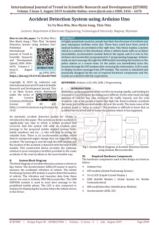
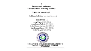
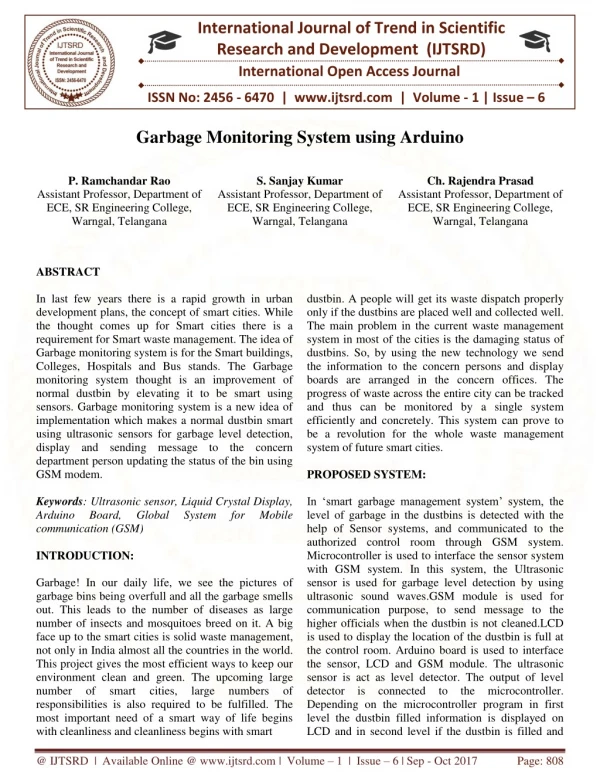
International Journal of Trend in Scientific Research and Development (IJTSRD) ISSN: 2456-6470 not at cleaned then message send to the higher officials. The AT commands are used to facilitate the messaging service through the GSM Module. This program is burned in the microcontroller with the help of Arduino software (IDE). These messages consist of information of garbage levels of respective dustbins. Depending on the information sent to control room, the authority informs the concern person of the respective area about garbage level. Then the concerned person makes sure that the garbage of that particular area is collected by sending the cleaning vehicles. HARDWARE REQUIREMENTS: The hardware requirements for the system are as follows. Ultrasonic Sensors: Detecting the level of Garbage. then presented to some form of decision device that calls the output either the required signal or noise. This decision device may be an operator with headphones or a display, or in some systems this function may be carried out by software. Further processes may be carried out to classify the target and localize it, as well as measuring its velocity. Some ultrasonic sensors have multiple beams to provide all round cover while others only cover an arrow arc, although the beam may be rotated, relatively slowly, by mechanical scanning. GSM Modem: GSM Modem can accept any GSM network operator SIM card and act just like a mobile phone with its own unique phone number. Advantage of using this modem will be that you can use itsRS232 port to communicate and develop embedded applications. Applications like SMS Control, data transfer, remote control and logging can be developed easily using GSM as shown below. Fig.1 Ultrasonic sensor The Ultrasonic Sensor sends out a high-frequency sound pulse and then times how long it takes for the echo of the sound to reflect back. The sensor has 2 openings on its front. One opening transmits ultrasonic waves, the other receives them. The speed of sound is approximately 341 meters (1100 feet) per second in air. The ultrasonic sensor uses this information along with the time difference between sending and receiving the sound pulse to determine the distance to an object. It uses the following mathematical equation: Distance = (Time x Speed of Sound)/2 Time = the time between when an ultrasonic wave is transmitted and when it is received. Fig.3 SIM900A GSM modem The modem can either be connected to Arduino microcontroller through RS232. It can be used to send and receive SMS or make/receive voice calls. It can also be used in GPRS mode to connect to internet and do many applications for data logging and control. This GSM modem is a highly flexible plug and play quad band SIM900A GSM modem for direct and easy integration to RS232applications. Supports features like Voice, SMS, Data/Fax, GPRS and integrated TCP/IP stack. Liquid Crystal Display: To display the dustbin location. Fig. 2 Ultrasonic sensor transmitting and receiving waves To measure the distance to an object, the time from transmission of a pulse to reception is measured and converted into arrange by knowing the speed of sound. This signal together with noise is then passed through various forms of signal processing, which for simple sensors may be just energy measurement. It is Fig.4 Liquid Crystal Display @ IJTSRD | Available Online @ www.ijtsrd.com | Volume – 1 | Issue – 6 | Sep - Oct 2017 Page: 809
International Journal of Trend in Scientific Research and Development (IJTSRD) ISSN: 2456-6470 Fig.5 Arduino Mega 2560 Board A liquid crystal display (LCD) is a display module with liquid crystals and backlight by LEDs. A 16x2 LCD display consists of two rows of display with each row consisting of 16 characters. LCD Module has 16 pins and operates with 5V. Power pins i.e. pins 1, 2, 3, 15 and 16 are used to supply for the module as well as the backlight LEDs. The voltage to the Contract Adjust Pin (Pin 3 or VEE) is usually given from a Potentiometer and will control the contrast of the actual display when the POT is adjusted. There are 8 data pins for transmitting 8bits of data i.e., 1 byte of data at a time. The LCD can be used in either 8bit mode or 4bit mode. The remaining three pins i.e. RS (Pin 4), RW (Pin 5) and E (Pin 6) are called the Control Pins and are very important pins. The RS pin, which is short for Register Select pin, is used to select either Instruction Register when it is LOW or Data Register when it is HIGH. The RW pin or the Read/Write Pin is used for selecting Read Mode or Write Mode. When RW is HIGH, read mode is selected and data is read from the register. When RW is LOW, write mode is selected and data can be written in to the register. Since we are using the write mode only, we can connect the RW pin to ground (through a pull down resistor). The Enable (E) pin, as the name indicates, is used to enable the execution of the data or instructions. The data or instruction are executed by the LCD module only when a HIGH to LOW pulse is given to the Enable pin i.e. only on the falling edge of a pulse. Arduino Mega 2560 Board: As shown in Fig.5 the Arduino Mega 2560 is a microcontroller board based on the ATmega2560. It has 54 digital input/output pins (of which 15 can be used as PWM outputs), 16 analog inputs, 4UARTs (hardware serial ports), a 16 MHz crystal oscillator, a USB connection, a power jack, an ICSP header, and a reset button. It contains everything needed to support the microcontroller; simply connect it to a computer with a USB cable or power it with an AC-to-DC adapter or battery to get started. The major advantage is control multiple appliances with a single board. SOFTWARE REQUIREMENTS: Arduino IDE: The Arduino is open source Integrated Development Environment or Arduino Software (IDE). It contains a text editor for writing code, a message area, a text console, a toolbar with buttons for common functions and a series of menus. Writing Sketches: Programs written using Arduino Software (IDE) are called sketches. These sketches are written in the text editor and are saved with the file extension .ino. The message area gives feedback while saving and exporting and also displays errors. The console displays text output by the Arduino Software (IDE), including complete error messages and other information. The bottom right hand corner of the window displays the configured board and serial port. The toolbar buttons allow you to verify and upload programs, create, open, and save sketches, and open the serial monitor. Arduino Language is user friendly and for programming is merely a set of C/C++ functions that can be called from your code. DESIGN AND IMPLEMENTATION: The project can be divided into two modules, one is detection of garbage level and then the second module is send the information to the corresponding officials through GSM. Fig. 6 Block diagram of Garbage monitoring system @ IJTSRD | Available Online @ www.ijtsrd.com | Volume – 1 | Issue – 6 | Sep - Oct 2017 Page: 810
International Journal of Trend in Scientific Research and Development (IJTSRD) ISSN: 2456-6470 FUTURE SCOPE: There is a great scope for the modifications of the Garbage monitoring system in future. The system can be improved by adding new functionalities like line follower robot to it, when the bin is full directly it is dumping on tipper. REFERENCES: 1)Marian Look, “Trash Plant: India”, earth 911B.National Conference Design(NCPD 2016), July 2016. 2)Basic Feature, “Solid waste Management Project by MCGM”. 3)Microtronics Technologies, “GSM based garbage and waste collection bins overflow indicator”, September 2013. 4)“Smart garbage management system”International Journal of Engineering Research &Technology (IJERT) ISSN:2278-0181. 5)“Smart Dustbin” National Conference on Product Design (NCPD 2016), July 2016. Fig. 7 Implementation of Garbage monitoring system Description of project: Garbage level detection is the done by ultrasonic sensors (HC-SR04).The ultrasonic sensors is placed on top of the dustbin facing the bottom. The sensors continuously emits the sonic waves, when the sonic waves hit the object and reflect back, the echo in the sensors senses the waves and calculates the distance of the object. Arduino Mega 2560 is used for controlling whole the process detecting garbage in different places and depending on the program first display in LCD to reminding the garbage level in the bin even though the garbage is not take out from the bin then the particular bin information is sent to higher officials through GSM. CONCLUSION: Garbage monitoring systems are the needs of Smart buildings. Smart waste monitoring and management is the keen idea of smart city planners. Garbage monitoring systems is a new idea of implementation which makes a normal dustbin smart using sensors for garbage level detection and sending message to the user updating the status of the bin. As soon as the dustbin is full it gives the information in LCD and sent the message to corresponding officials. on Product @ IJTSRD | Available Online @ www.ijtsrd.com | Volume – 1 | Issue – 6 | Sep - Oct 2017 Page: 811