Download
1 / 9
90 likes | 113 Vues
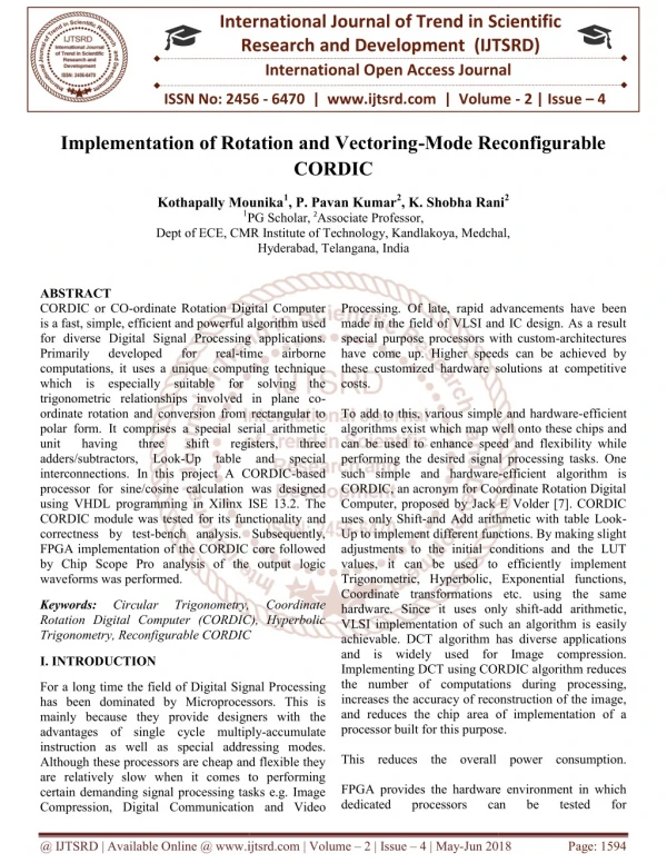
CORDIC or CO ordinate Rotation Digital Computer is a fast, simple, efficient and powerful algorithm used for diverse Digital Signal Processing applications. Primarily developed for real time airborne computations, it uses a unique computing technique which is especially suitable for solving the trigonometric relationships involved in plane co ordinate rotation and conversion from rectangular to polar form. It comprises a special serial arithmetic unit having three shift registers, three adders subtractors, Look Up table and special interconnections. In this project A CORDIC based processor for sine cosine calculation was designed using VHDL programming in Xilinx ISE 13.2. The CORDIC module was tested for its functionality and correctness by test bench analysis. Subsequently, FPGA implementation of the CORDIC core followed by Chip Scope Pro analysis of the output logic waveforms was performed. Kothapally Mounika | P. Pavan Kumar | K. Shobha Rani "Implementation of Rotation and Vectoring-Mode Reconfigurable CORDIC" Published in International Journal of Trend in Scientific Research and Development (ijtsrd), ISSN: 2456-6470, Volume-2 | Issue-4 , June 2018, URL: https://www.ijtsrd.com/papers/ijtsrd14396.pdf Paper URL: http://www.ijtsrd.com/engineering/electronics-and-communication-engineering/14396/implementation-of-rotation-and-vectoring-mode-reconfigurable-cordic/kothapally-mounika<br>

E N D
International Research Research and Development (IJTSRD) International Open Access Journal International Open Access Journal International Journal of Trend in Scientific Scientific (IJTSRD) ISSN No: 2456 ISSN No: 2456 - 6470 | www.ijtsrd.com | Volume 6470 | www.ijtsrd.com | Volume - 2 | Issue – 4 Implementation of Rotation and Vectoring Implementation of Rotation and Vectoring-Mode Reconfigurable CORDIC Mode Reconfigurable Kothapally Mounika Kothapally Mounika1, P. Pavan Kumar2, K. Shobha Rani PG Scholar,2Associate Professor, Dept of ECE, CMR Institute of Technology, Kandlakoya, Medchal, Hyderabad, Telangana, India Shobha Rani2 1PG Scholar, Dept of ECE, CMR Institute of Technology, Kandlakoya, Medchal, Dept of ECE, CMR Institute of Technology, Kandlakoya, Medchal, ABSTRACT CORDIC or CO-ordinate Rotation Digital Computer is a fast, simple, efficient and powerful algorithm for diverse Digital Signal Processing applications. Primarily developed for computations, it uses a unique computing technique which is especially suitable for solving the trigonometric relationships involved in plane co ordinate rotation and conversion from rectangular to polar form. It comprises a special serial arithmetic unit having three adders/subtractors, Look-Up table and special interconnections. In this project A CORDIC processor for sine/cosine calculation was designed using VHDL programming in Xilinx ISE 13.2. The CORDIC module was tested for its functionality correctness by test-bench analysis. Subsequently, FPGA implementation of the CORDIC core followed by Chip Scope Pro analysis of the waveforms was performed. ordinate Rotation Digital Computer is a fast, simple, efficient and powerful algorithm used for diverse Digital Signal Processing applications. Processing. Of late, rapid advancements have been made in the field of VLSI and IC design. As a result special purpose processors with custom have come up. Higher speeds can be achieved by these customized hardware solutions at competitive costs. To add to this, various simple and hardware algorithms exist which map well onto these chips a can be used to enhance speed and flexibili performing the desired signal processing tasks. One such simple and hardware CORDIC, an acronym for Coordinate Rotation Digital Computer, proposed by Jack E Volder [7]. CORDIC uses only Shift-and Add arithmetic with table Look Up to implement different functions. By making slight adjustments to the initial conditions and the LUT values, it can be used to efficiently implement Trigonometric, Hyperbolic, Exponential functions, Coordinate transformations hardware. Since it uses only shift VLSI implementation of such an achievable. DCT algorithm has diverse applications and is widely used for Image compression. Implementing DCT using CORDIC algorithm reduces the number of computations during increases the accuracy of reconstruction of the image, and reduces the chip area of implementation of a processor built for this purpose. This reduces the overall FPGA provides the hardware environment in which dedicated processors dedicated processors Processing. Of late, rapid advancements have been made in the field of VLSI and IC design. As a result purpose processors with custom-architectures have come up. Higher speeds can be achieved by these customized hardware solutions at competitive real-time time airborne airborne computations, it uses a unique computing technique which is especially suitable for solving the trigonometric relationships involved in plane co- otation and conversion from rectangular to polar form. It comprises a special serial arithmetic unit having three To add to this, various simple and hardware-efficient algorithms exist which map well onto these chips and can be used to enhance speed and flexibility while signal processing tasks. One shift shift Up table and special registers, registers, three three interconnections. In this project A CORDIC-based e calculation was designed programming in Xilinx ISE 13.2. The CORDIC module was tested for its functionality and bench analysis. Subsequently, -efficient algorithm is CORDIC, an acronym for Coordinate Rotation Digital Computer, proposed by Jack E Volder [7]. CORDIC and Add arithmetic with table Look- Up to implement different functions. By making slight adjustments to the initial conditions and the LUT values, it can be used to efficiently implement Trigonometric, Hyperbolic, Exponential functions, CORDIC core followed output logic etc. using the same uses only shift-add arithmetic, of such an algorithm is easily DCT algorithm has diverse applications and is widely used for Image compression. ng CORDIC algorithm reduces e number of computations during processing, increases the accuracy of reconstruction of the image, and reduces the chip area of implementation of a processor built for this purpose. Keywords: Rotation Digital Computer (CORDIC), Hyperbolic Trigonometry, Reconfigurable CORDIC Trigonometry, Reconfigurable CORDIC Circular Circular Trigonometry, Trigonometry, Coordinate Coordinate Rotation Digital Computer (CORDIC), Hyperbolic I. INTRODUCTION For a long time the field of Digital Signal P has been dominated by Microprocessors. This is mainly because they provide designers with the advantages of single cycle multiply instruction as well as special addressing modes. Although these processors are cheap and flexible they are relatively slow when it comes to performing certain demanding signal processing tasks e.g. Image Compression, Digital Communication Communication and Video For a long time the field of Digital Signal Processing Microprocessors. This is esigners with the single cycle multiply-accumulate cial addressing modes. these processors are cheap and flexible they are relatively slow when it comes to performing certain demanding signal processing tasks e.g. Image This reduces the overall power consumption. FPGA provides the hardware environment in which can can be be tested tested for for @ IJTSRD | Available Online @ www.ijtsrd.com Available Online @ www.ijtsrd.com | Volume – 2 | Issue – 4 | May-Jun 2018 Jun 2018 Page: 1594
International Journal of Trend in Scientific Research and Development (IJTSRD) ISSN: 2456-6470 their functionality. They perform various high-speed operations that cannot simple microprocessor. The primary advantage that FPGA offers is On-site programmability. Thus, it forms the ideal platform to implement and test the functionality of a dedicated processor designed using CORDIC algorithm. Window filtering techniques are commonly employed in signal processing paradigm to limit time and frequency resolution. Various window functions are developed to suit different requirements for side-lobe minimization, dynamic Commonly, many hardware efficient architectures are available for realizing FFT, but the same is not true for windowing–architectures. hardware implementation of window functions uses lookup tables which give rise to various area and time complexities with increase in word lengths. Moreover, they do not allow user-defined variations in the window length. An efficient implementation of flexible and reconfigurable window functions using CORDIC algorithm is suggested. Though they allow user-defined variations in window length, latency is a major problem. The CORDIC algorithm inherently suffers from latency issues and using two CORDIC processors in series, as is done. The overall latency of the system is hampered. variable length and speed. Basic idea of this work is to propose a flexible and fast architecture for Blackman windowing function to fit with the advanced FFT processor. Before presenting the proposed architecture in the next section, Blackman windowing function has been highlighted here briefly. A typical block diagram for real time FFT based spectral analysis system is shown in Fig.1. be realized by a range, and so forth. The conventional Fig.1. Spectral analysis system The Blackman window, with the above approximation coefficients, provide attenuation of at least 60dB of side lobes[1] with only a modest increase in computation over that required by the Hanning and Hamming window due to another cosine term as in equation (2). This windowing function demands the attention for designing hardware efficient, flexible window length setting and high throughput VLSI architecture using CORDIC whose implementation is quite economic in terms of hardware. Now from equation (2), we shall have a parallel and pipelined architecture for aforesaid windowing function, where the selection of window length (N) is user defined as per requirement for the application. Since the equation needs trigonometric implementation using CORDIC algorithm is better choice in terms of computation and to change the value of N dynamically. But look up table or ROM method fails to achieve the same. In case of fixed N also, though existing implementation is based on look up table, it consumes more time to access the ROM and to compute multiplication and addition. Whereas CORDIC based proposed architecture gives same result with high throughput and lesser hardware compared to ROM based computation. Here multiplication and trigonometric computations are realized using linear and circular CORDIC algorithm respectively. II. LITERATURE SURVEY During spectral analysis, the input signals are to be truncated to fit a finite observation window according to the length of FFT processor. This direct truncation using conventional windowing, known as rectangular window function leads to undesirable effects known as spectral leakage and picket fence effect in frequency domain. To minimize these effects during spectral analysis, researchers have proposed different kinds of windowing functions such as Hanning, Hamming and Blackman windowing functions. These windowing functions are widely adopted because of their good spectral characteristics like central peak width, 6-dB point, highest side lobe and rate of side lobe fall off and equivalent noise bandwidth (ENBW). Among these, Blackman windowing leads to better side lobe attenuation. It is needless to present all these characteristics in detail here, however readers may refer for the same. Here only Blackman windowing has been discussed for implementation. Though ROM based implementation is already existing, which restricts flexible implementation and also restricts fitting with the advanced FFT processors in terms of computation, so the @ IJTSRD | Available Online @ www.ijtsrd.com | Volume – 2 | Issue – 4 | May-Jun 2018 Page: 1595
International Journal of Trend in Scientific Research and Development (IJTSRD) ISSN: 2456-6470 limitations, followed by the discussions on our design strategy for a reconfigurable CORDIC. 1) Scaling-Free CORDIC Algorithm and Its Limitations: The scaling-free CORDIC [2] employs second-order Taylor series approximation, where the rotation matrix is given by This approximation imposes a restriction on the basic- shift1i =[(b−2.585/3)]. For 16-bit applications, the basic-shift is i =4, which reduces the RoC to 7.16°, which can be extended to 22.5° using multiple iterations corresponding to the basic-shift i =4. This is a major drawback, which limits the applicability of this algorithm. Moreover, the algorithms focus only on circular rotation-mode, which cannot be directly extended to hyperbolic CORDIC, since the second order of approximation of Taylor series expansion of hyperbolic functions results in a very low RoC (nearly 22.5°). Due to the lack of symmetry in hyperbolic functions, the RoC cannot be extended to the entire coordinate space. 2) Reconfigurability of Rotation-Mode CORDIC: Scaling-free algorithms for circular and hyperbolic trajectories are proposed. Moreover, in both the scaling-free algorithms, third order of approximation of Taylor series is used to derive the CORDIC rotation-matrices, as Fig.2. Block representation for spectral analysis III. PROPOSED SYSTEM RECONFIGURABLE CORDIC To design a reconfigurable CORDIC architecture with minimum reconfiguration overhead, we need to maximize the sharing of common hardware circuit in different configurations. Therefore, to explore the possibility of reconfigurable CORDIC, we examine, here, the commonalities in three main issues of CORDIC implementation, namely: 1) the coordinate- rotation matrix; 2) selection of elementary angles; and 3) direction of micro rotations. A. Reference Reconfigurable CORDIC A basic design for reconfigurable CORDIC based on unified CORDIC algorithm was proposed. The major concern with the design reconfigurable architecture is the incompatibility in RoC of circular and hyperbolic trajectories. The RoC of circular CORDIC is [−99°, 99°], while that of hyperbolic CORDIC is given by |θ|≤1.1182 radians. This limits the maximum angle of rotation of the reconfigurable design to 64°. The incompatible RoC of circular and hyperbolic CORDICs makes it difficult to implement them in the same circuit to perform rotation through [−180°, 180°]. Another major issue with the conventional reconfigurable CORDIC is scaling. We need to have two different scaling circuits for circular and hyperbolic CORDIC, and select the output from one of the scaling circuits depending on the selection of trajectory of operation. of conventional Fig.3. Proposed reconfigurable rotation-mode CORDIC processor. B. Design Strategy for Proposed Reconfigurable CORDIC The circular and hyperbolic CORDICs require two different scaling circuits, which is quite costly. Therefore, it is necessary to use a scale-free implementation in the reconfigurable CORDIC. Here, we discuss the scaling-free CORDIC and its Note that the same set of elementary angles is used for both circular and hyperbolic rotation-modes. This is a big advantage to derive the reconfigurable CORDIC, since no differentiation is required to identify the micro rotations according to the trajectories. For @ IJTSRD | Available Online @ www.ijtsrd.com | Volume – 2 | Issue – 4 | May-Jun 2018 Page: 1596
International Journal of Trend in Scientific Research and Development (IJTSRD) ISSN: 2456-6470 circular and hyperbolic trajectories, the elementary angles are redefined as A.Rotation-Mode Reconfigurable CORDIC The proposed design for reconfigurable rotation-mode CORDIC (shown in Fig. 3) consists of three parts: 1) preprocessing unit; 2) reconfigurable CORDIC rotation unit; and 3) post processing unit. The preprocessing unit ensures that the input rotation angle to the CORDIC processing structure always lies in the range [0,π/4], as the maximum rotation angle that can be handled by micro rotation sequence generator is π/4. The post processing unit is required only for circular trajectory to swap/complement the sine/cosine values depending on the octant of the rotation angle. The user can control the trajectory of the reconfigurable CORDIC by changing a 1-bit signal T. The rotation matrix for reconfigurable rotation-mode CORDIC is obtained after unifying the rotation matrices of circular and hyperbolic case given by (4a) and (4b), respectively, as Whereas i is the number of shifts for the ith iteration. The RoC for both the trajectories is compatible and extends to the entire coordinate space. The design for rotation-mode CORDIC with slight modification can be extended to support vectoring- mode as discussed below 3) Re configurability of Vectoring-Mode CORDIC: To realize a vectoring-mode CORDIC, all the micro rotations will be performed in the clockwise direction for both the circular and hyperbolic trajectories. The rotation matrices are given by Whereas i is the shift-index ith iteration . The sign-bit of the y-coordinate over successive iterations determines the angle of rotation θ. For vectoring- mode, the maximum angle of rotation that can be computed lies in the range [0,π/4]. However, this range can be extended to the entire coordinate space using octant wave symmetry of sine and cosine functions for circular trajectory. Where T= 0 hyperbolic T=1 circular Proposed Reconfigurable CORDIC: The coordinate calculation matrices for circular and hyperbolic CORDICs differ by the sign of operands, and to realize that additions are to be replaced by subtractions and vice-versa. This can be easily realized by a reconfigurable add/subtract circuit. In both cases, the basic-shift could be either 2 or 3, but the number of micro rotations varies with the mode of operation. Besides, each case will have its own circuit to enable the extension of RoC. Based on these observations, we design CORDIC architectures: Fig.4. Structure of the proposed reconfigurable recursive CORDIC architectures. 1)Proposed Recursive Architecture: The recursive architecture (shown in Fig. 4) uses a single CORDIC micro rotator to perform all the CORDIC iterations. The circular CORDIC of requires one iteration less than the hyperbolic CORDIC, but here we realize the architecture for the same number of iterations (eight for sbasic=2 and eleven forsbasic=3) for both circular and hyperbolic trajectories. The reconfigurable coordinate calculation unit (RCCU) isshowninFig.3. three reconfigurable 1)rotation-mode reconfigurable CORDIC; 2)vectoring-mode reconfigurable CORDIC; 3)generalized reconfigurable CORDIC. @ IJTSRD | Available Online @ www.ijtsrd.com | Volume – 2 | Issue – 4 | May-Jun 2018 Page: 1597
International Journal of Trend in Scientific Research and Development (IJTSRD) ISSN: 2456-6470 mode. The rollover counter value is 15 for sbasic=2, and 17 forsbasic=3. The pipelined architecture of vectoring-mode reconfigurable CORDIC consists of eight stages for sbasic = 2, as shown in Fig. 7. Fig.5. RCCU for recursive design 2. Proposed Pipelined Architecture: Fig. 6 shows the reconfigurable CORDIC rotation unit for basic-shift 2. The shift-index si Is fixed in every RCCU, and hence the shifters are hardwired and do not involve high complexity barrel-shifters. The implementation of RCCUs varies according to the basic-shift si. With slight modifications, the pipeline can be extended for basic-shift 3. Fig 7 Proposed pipeline reconfigurable vectoring- mode CORDIC unit for sbasic=2 Similar to reconfigurable rotation-mode CORDIC, for increasing shift-indices, the implementation of RCCUs is simplified for reconfigurable vectoring- mode CORDIC as well. The input coordinates [Xin’,Yin’] are first preprocessed coordinates[xin,yin] and octant mapping signals. The coordinates [xin,yin]are input to the vectoring-mode CORDIC pipeline to generate an angle θ ∈[0,π/4]. The rotation angle θ generated by the vectoring-mode CORDIC pipeline is mapped to the desired octant using the octant mapping signals generated by the preprocessing unit. Therefore, the RoC supported by the proposed vectoring-mode reconfigurable CORDIC is [−π, π]. C. Proposed Generalized Reconfigurable CORDIC The generalized reconfigurable CORDIC can operate either in vectoring-mode or in rotation- mode for both circular and hyperbolic trajectories. The user can select the trajectory of operation using a single bit signal T(T=1 for circular and T=0 for hyperbolic). Another single bit signal M is used to control the mode of operation (M=0 for rotation-mode and M=1 for vectoring-mode). The recursive architecture of the reconfigurable CORDIC combining the CORDIC micro rotators for both rotation-mode and vectoring-mode CORDICs, as shown in Fig. 8. The throughput of the proposed recursive generalized reconfigurable CORDIC is the same as that of the recursive reconfigurable vectoring- mode CORDIC. The block diagram for pipelined generalized reconfigurable CORDIC using basic- shifts basic=2 is shown in Fig. 9. It can be easily extended to basic-shifts basic=3 as is done for to obtain Fig.6. Reconfigurable rotation-mode CORDIC unit for basic-shift 2 B. Reconfigurable Vectoring-Mode CORDIC The reconfigurable rotation matrix for vectoring mode is obtained by unifying (6a) and (6b), as proposed is generalized implemented by Where T=0 hyperbolic ----8 T=1 circular By changing the implementation of the RCCU to implement, the recursive architecture of Fig. 2 can be used to realize CORDIC iterations for vectoring- @ IJTSRD | Available Online @ www.ijtsrd.com | Volume – 2 | Issue – 4 | May-Jun 2018 Page: 1598
International Journal of Trend in Scientific Research and Development (IJTSRD) ISSN: 2456-6470 reconfigurable rotation-mode and vectoring-mode CORDICs. IV.EXTENSION WORK Blackman window architecture Fig.8. Structure of CORDIC micro rotator for the proposed recursive generalized reconfigurable CORDIC. Fig. 10 Pipelined CORDIC Architecture (a) Circular (b) linear A high throughput VLSI architecture for Blackman windowing. Since most of the implementation of windowing functions for real time applications, are based on either ROM or DSP processor. Here the proposed architecture is designed using major blocks like CORDIC(CO-ordinate Computer) and Han-Carlson adder. This architecture is flexible in terms of window length. So that a single chip can be used for those applications, where variable length is required. The architecture is shown in Fig.10 for VLSI implementation of Blackman windowing function. Major blocks of proposed architecture are described subsequently. Two linear CORDIC blocks are used for multiplying input samples with constant coefficients (b0and b2), however the multiplication of constant coefficient (b1=0.5) with input samples is done with only hard shifter (1-bit right) and passes through FIFO_1 for synchronization with other parallel paths and similarly FIFO_2 is also used for synchronization. Circular CORDIC has been used to compute cosine functions given in equation (2) and multiplication of intermediate values (i.e. values from lower linear CORDIC and FIFO_1 as shown in Fig.10). CORDIC blocks used in our proposed architecture are purely pipelined, where add/sub Rotation DIgital Fig.9. Proposed pipeline generalized reconfigurable CORDIC unit for sbasic=2. @ IJTSRD | Available Online @ www.ijtsrd.com | Volume – 2 | Issue – 4 | May-Jun 2018 Page: 1599
International Journal of Trend in Scientific Research and Development (IJTSRD) ISSN: 2456-6470 circuit is the critical path. Here length of FIFOs is equal to the number of stages of pipelined CORDIC minus one, e.g, for 16-bit precision CORDIC, the number of stages are sixteen and thus FIFO length to be fifteen. TECHNOLOGICAL SCHEMATIC: SIMULATION RESULTS: Figure: Technology schematic of proposed system Fig: Simulation result of proposed system Design summary: The following figure includes all the design summary of the proposed method. RTL SCHEMATIC: Figure: Design summary of proposed system TIMING REPORT: Fig: RTL Schematic of proposed system The above diagram shows that RTL Schematic for the proposed method. The number of gates and other design summary is included in the following table which can be followed by the technological diagram of the proposed method. Figure: Timing Report of proposed system @ IJTSRD | Available Online @ www.ijtsrd.com | Volume – 2 | Issue – 4 | May-Jun 2018 Page: 1600
International Journal of Trend in Scientific Research and Development (IJTSRD) ISSN: 2456-6470 Design summary: The following Figure includes all the design summary of the Extension method. EXTENSION RESULTS: Figure: Simulation results of extended system RTL SCHEMATIC: Fig: Design summary of extended system TIMING REPORT: Figure. RTL schematic of extended system The above diagram shows that RTL Schematic for the Extension method. The number of gates and other design summary is included in the following table which can be followed by the technological diagram of the Extension method. Fig: Timing report of extended system TECHNOLOGICAL SCHEMATIC: Comparison Table The following diagram show that the entire comparison between proposed method and extension method. Design Slices LUT s Proposed 1650 2876 Delay (ns) 183.4 60ns 161.3 50ns IOB’S 35 Extension 1300 2438 35 Fig;: Comparison between proposed system and extended system. Figure: Technology schematic of extended system @ IJTSRD | Available Online @ www.ijtsrd.com | Volume – 2 | Issue – 4 | May-Jun 2018 Page: 1601
International Journal of Trend in Scientific Research and Development (IJTSRD) ISSN: 2456-6470 9)Ahmed,H.M.,Delosme,J.M.,andMorf,M.,"Highly Concurrent Computing Structure for Matrix Arithmetic and Signal Processing," IEEE Comput. ag,,Vol.15,1982,pp.65-82. V.CONCLUSION CORDIC is a powerful algorithm, and a popular algorithm of choice various Digital Signal Processing applications. Implementation of a CORDIC-based processor on FPGA gives us a powerful mechanism implementing complex computations on a platform that provides a lot of resources and flexibility at a relatively lesser cost. Further, since the algorithm is simple and efficient the design implementation of a CORDIC based processor is easily achievable. In this project a CORDIC module is designed and simulated using Xilinx ISE using VHDL as a synthesis tool. The output of the CORDIC core is analyzed and verified on the test-bench. when it comes to 10)Depreterre, E.,Dewilde, P.,and Udo, R.,'Pipelined CORDIC Architecture Filtering and Array Processing," Proc.ICASSP'84, 1984,pp.41.A.6.1-41.A.6.4. of for Fast VLSI and VLSI Author’s Profile: Kothapally Mounika is currently pursuing MTECH in VLSI system design in CMR Technology, Kandlakoya, Medchal, Hyderabad. She bachelor’s degree in Electronics and Communication Engineering in 2015 from Stanley College of engineering and technology for women affiliated to Osmania University, Hyderabad. Her current research interests include very large scale integration (VLSI) low power design. P. Pavan Kumar working as a Associate Professor in CMR Institute Medchal, Hyderabad. His current research interests include very large scale integration (VLSI) low power design, test automation and fault- tolerant computing. K. Shobha Rani is currently working as a Associate Professor in CMR Institute of Technology, Medchal, Hyderabad. Her current research interests include very large scale integration (VLSI) low power design, high performance architectures and VLSI reliability. Institute of REFERENCES received her 1)Ray Andraka, FPGA '98. Proceedings of the 1998 ACM/SIGDA sixth symposium on Field programmable gate arrays, Feb. 22-24, 1998, Monterey, CA. pp191-200 international 2)Vikas Sharma,"FPGA Implementation of EEAS CORDIC based Generator",M.Tech Thesis, Comm. Eng.,Thapar Uni., Patiala, 2009. Sine and Dept. Cosine Electron. is currently 3)Satyasen Design Processor using CORDIC Algorithm",M.Tech Thesis,Dept. Rourkela, Rourkela, Orissa,2010. Panda,"Performance of a Discrete Analysis and of Technology, Cosine Transform Electron.Comm.Eng.,NIT 4)Kris Raj, Gaurav Doshi, Hiren Shah [online] Available: http://teal.gmu.edu/courses/ECE645/projects_S06/ talks/CORDIC.pdf(URL) 5)S.K.Pattanaik and K.K.Mahapatra, "DHT Based JPEG Image Compression Using a Novel Energy Quantization Method", IEEE International Conference on Industrial Technology,pp.2827- 2832,Dec 2006. 6)Volder, J.,"Binary Computation Algorithms for coordinate rotation generation,"Convair Aeroelectrics Group, June 1956. and function IAR-1148 Report 7)Volder, Computing Computing, Vol EC-8, pp330-334 Sept 1959. J.,"The Technique,"IRE CORDIC Trigonometric Trans.Electronic 8)Walther J.S.,"A unified algorithm for elementary functions," Spring Conf.,1971,proc.,pp.379-385. Joint Computer @ IJTSRD | Available Online @ www.ijtsrd.com | Volume – 2 | Issue – 4 | May-Jun 2018 Page: 1602