Download
1 / 3
30 likes | 70 Vues
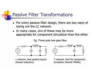
Second and third order passive filters LC and LCL are interesting filters to use for grid connected PWM inverters. Because of the stability problems of this filter around resonance frequency, series and damping resistor can be add to an LCL filter. However, the resistor value has impact on the filter respond, voltage and current harmonic distortion and system power loss. In this paper, the mathematic characteristics of LC, LCL filter, series and parallel damping LCL filters will be described with their design to apply in 3 phase PV grid connected inverter. And, simulations are used to validate the theoretical analysis of the filters on filter performance and power quality of the grid in 3 phase grid connected inverter. P.Kamalakar "Passive Damping Filter Design and Application for Three-Phase PV Grid-Connected Inverter" Published in International Journal of Trend in Scientific Research and Development (ijtsrd), ISSN: 2456-6470, Volume-1 | Issue-6 , October 2017, URL: https://www.ijtsrd.com/papers/ijtsrd2495.pdf Paper URL: http://www.ijtsrd.com/engineering/electrical-engineering/2495/passive-damping-filter-design-and-application-for-three-phase-pv-grid-connected-inverter/pkamalakar<br>

E N D
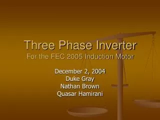
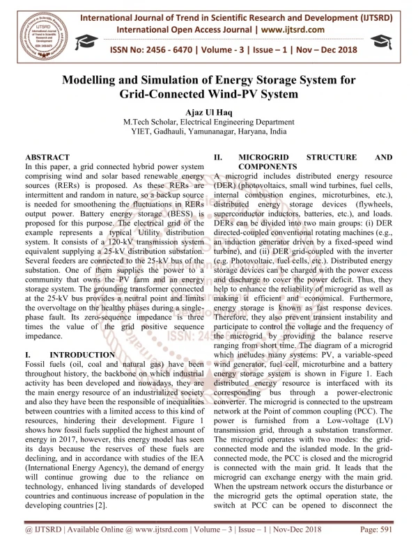
International Research Research and Development (IJTSRD) International Open Access Journal Passive Damping Filter Design and Application f Phase PV Grid-Connected Inverter International Journal of Trend in Scientific Scientific (IJTSRD) International Open Access Journal ISSN No: 2456 ISSN No: 2456 - 6470 | www.ijtsrd.com | Volume 6470 | www.ijtsrd.com | Volume - 1 | Issue – 6 Passive Damping Filter Design and Application for Passive Damping Filter Design and Application f Three-Phase PV Connected Inverter P.Kamalakar M.Tech, Research Scholar, M.Tech, Research Scholar, Department of EEE ABSTRACT Second and third-order passive filters (LC and LCL) are interesting filters to use for grid-connected inverters. Because of the stability problems of this filter around resonance frequency, series and damping resistor can be add to an LCL filter. However, the resistor value has impact on the filter respond, voltage and current harmonic distortion and loss. In this paper, the mathematic characteristics of LC, LCL filter, series and parallel damping LCL filters will be described with their design to apply in 3-phase PV grid-connected inverter. And, simulations are used to validate the theoretical analysis of the filters on filter performance and power quality of the grid in 3-phase grid-connected inverter. filter is high due to the additional cost of the sensors and control system. Because of the low cost and simple circuit in a stiff grid application, a passive damping strategy is more preferred. A simple damped LCL filter is an LCL filter with series or parallel resistor with capacitor. By adding a resistor to the filter circuit, the power loss will increase. So, finding the optimum resistor value to decrease the peak resonance of LCL filter is very important. Therefore, in this paper characteristics of LC, LCL filter, series and parallel damping LCL filters will be discussed. power quality is important for the reliable operation of the system and loads [9], these filters will be applied to a three-phase PV system. Then, the inverter output will be filtered in order to obtain low voltage and current distortion. pacts of the resistor value on the filter respond and also current and voltage harmonic will be filter is high due to the additional cost of the sensors and control system. Because of the low simple circuit in a stiff grid application, a passive damping strategy is more preferred. A simple damped LCL filter is an LCL filter with series or parallel resistor with capacitor. By adding a resistor to the filter circuit, the power loss will the optimum resistor value to decrease the peak resonance of LCL filter is very important. Therefore, in this paper characteristics of LC, LCL filter, series and parallel damping LCL filters will be discussed. Since maintaining a good power quality is important for the reliable operation of the system and loads [9], these filters will be applied to a three system. Then, the inverter output will be filtered in order to obtain low voltage and current distortion. And also, the impacts of the resistor value on the filter respond and also current and voltage harmonic will be discussed. order passive filters (LC and LCL) connected PWM inverters. Because of the stability problems of this filter around resonance frequency, series and damping resistor can be add to an LCL filter. However, the resistor value has impact on the filter respond, voltage and current harmonic distortion and system power loss. In this paper, the mathematic characteristics of LC, LCL filter, series and parallel damping LCL filters will be described with their design to apply in connected inverter. And, simulations tical analysis of the filters on filter performance and power quality of the I. INTRODUCTION Filters are main parts of a renewable energy system. First- order passive filters are L type which are generally use for controlling grid-connected inverter. The disadvantage of this type of filters is their big size. Another type of the passive filters is LC filters (second-order). Because of the big size of the inductor, the size of this filter is large. Moreover, time delay and resonance frequency are another drawbacks of LC filters. Compared with a first-order and second order filters, a third-order LCL filter has lower coast and smaller size in applications above several kilowatts. However, resonance frequency is still as a problem of these filters. To repress the resonances of an LCL filter, active damping [1]–[4] or passive damping [5]–[8] can be used. The price for active [8] can be used. The price for active Filters are main parts of a renewable energy system. order passive filters are L type which are connected inverter. The disadvantage of this type of filters is their big size. Another type of the passive filters is LC filters order). Because of the big size of the inductor, the size of this filter is large. Moreover, time and resonance frequency are another drawbacks order and second- order LCL filter has lower coast and smaller size in applications above several kilowatts. However, resonance frequency is still as a problem of these filters. To repress the resonances of [4] or passive @ IJTSRD | Available Online @ www.ijtsrd.com @ IJTSRD | Available Online @ www.ijtsrd.com | Volume – 1 | Issue – 6 | Sep - Oct 2017 Oct 2017 Page: 346
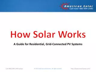
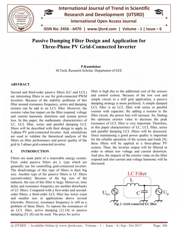
International Journal of Trend in Scientific Research and Development (IJTSRD) ISSN: 2456-6470 gridconnected application is designed. In these simulations a tuned PI controller is implemented to control the grid side voltage. Then, Ki is determined as 1.585. So, the rise time will be equal to 1.39 Sec and setting time 2.47 Sec. Time domain response for this tuned PI controller is shown in Fig. When, the system rated power is 20 kW, the line voltage is 240 V, the switching frequency is 2 kHz and the fundamental frequency is 60 Hz. Choosing the cut-off frequency of 100 Hz for a 2 kHz switching frequency from (4), the inverter’s expected maximum load current of 200 A and the output phase voltage of 200 V , the values of L and C determined for the model were 60 mH and 42.22 µF respectively using (4) - (6) formulas. II. PRINCIPLE OF PASSIVE FILTERS First, grid-connected converters are the interface to connect renewable energy sources to the power system. To reduce the harmonics injected by the converters a high value of input inductance should be used. However, L filter design is easy but in application above several kilowatts it becomes expensive because of using large filter reactor. Moreover, the system dynamic response becomes poor. A. LC Filter The filter consists of an inductance in series with the inverter and a capacitance in parallel with the grid (Fig. 1). By using this parallel capacitance, the inductance can be reduced, thus reducing costs and losses compare with L filter. By using a large capacitance, other problems such as high inrush currents and high capacitance current at the fundamental frequency or dependence of the filter on the grid impedance for overall harmonic attenuation will appear [10]. III. FILTER DESIGN A typical low pass LC filter is shown in Fig.1. The LC low pass filter is a second order filter which eliminates all high order harmonics from the PWM output of the inverter so that the input voltage of the grid become a pure sinusoidal wave of 60 Hz. The cut-off frequency (fc) of the low pass filter is selected such that the output voltage THD is less than 5% [12]. The attenuation effect of LC filters can be increased by decreasing the filter cut-off frequency against the switching frequency of inverters according to -40log ( cutt off sw f f ) as it indicated in Fig.2. However, the filter cut-off frequency limits the control band-width of inverter systems. Increasing the control bandwidth is important for fast operation of the inverter system and also for precise voltage compensation without a phase delay at higher-order harmonics. Thus, there is a trade-off between the attenuation effect and the control bandwidth in the design of LC filters. Generally, the value of fc is kept below 1/10th of the inverter switching frequency [13]. The selection of the filter inductance, Lf, should be such that the voltage drop across the inductor is less than 3% of the inverter output voltage [14]. Then, the value of L can be calculated using (4) - (6). V. CONCLUSION A 20 kW three-phase grid-connected inverter with a PI tuned controller is implemented to validate the designed LC, LCL and damped LCL filters and compared their performance. Based on the simulation results, it can been seen with the same resistor value, the parallel resistor damped LCL filter has better action at resonance frequency compare with series damped LCL filter. And, the voltage and current of the grid show less harmonic distortion for this damped filter. In fact, the parallel damped LCL filter has the best design to filter the harmonics for gridconnected renewable energy systems. RERFERENCES 1)Y. Tang, P. Loh, P. Wang, F. Choo, F. Gao, and F. Blaabjerg, “Generalized performance shunt active power filter with output LCL-filter,” IEEE Trans. 1 nd. Electron., vol. 59, no. 3, pp. 1443–1452, Mar. 2012. 2)Y. Tang, P. Loh, P. Wang, F. Choo, and F. Gao, “Exploring inherent damping characteristic of LCL-filters for three-phase grid-connected voltage source inverters,” IEEE Trans. Power Electron., vol. 27, no. 3, pp. 1433– 1443, Mar. 2012. design of high IV. SIMULATION RESULTS The SIMULINK in MATLAB software is used to simulate the system which is shown in Fig.11. In this paper, the simulation for all filter types in PV @ IJTSRD | Available Online @ www.ijtsrd.com | Volume – 1 | Issue – 6 | Sep - Oct 2017 Page: 347
International Journal of Trend in Scientific Research and Development (IJTSRD) ISSN: 2456-6470 3)J. Dannehl, M. Liserre, and F. W. Fuchs, “Filter- based active damping of voltage source converters with LCL filter,” IEEE Trans. I nd.Electron., vol. 58, no. 8, pp. 3623–3633, Aug. 2011. 4)A. Cagnano, E. De Tuglie, M. Liserre, and R. A. Mastromauro, “Online optimal reactive power control strategy of PV inverters,” IEEE Trans. Ind. Electron., vol. 58, no. 10, pp. 4549–4558, Oct. 2011. 5)T. C. Y. Wang, Z. Ye, G. Sinha, and X. Yuan, “Output filter design for a grid-interconnected three-phase inverter,” in Proc. PESC , Acapulco, NM, Jun. 15–19, 2003, pp. 779–784. 6)R. Turner, S. Walton, and R. Duke, “Stability and bandwidth implications of digitally controlled grid-connected parallel inverters,” IEEE Trans. Power Electron., vol. 57, no. 11, pp. 3685–3694, Nov. 2010. 7)A. A. Rockhill, M. Liserre, R. Teodorescu, and P. Rodriguez, “Grid-filter multimegawatt medium-voltage voltage-source inverter,” IEEE Trans. I nd.Electron., vol. 58, no. 4, pp. 1205–1217, Apr. 2011. design for a @ IJTSRD | Available Online @ www.ijtsrd.com | Volume – 1 | Issue – 6 | Sep - Oct 2017 Page: 348