FPGA Climatic
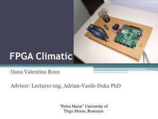
FPGA Climatic. Oana Valentina Rusu Advisor: Lecturer eng. Adrian- Vasile Duka PhD . “Petru Maior” University of Tirgu Mures, Romania. Contents. Introduction Project overview HDL Design Software Design Conclusions Demo. Introduction. It is a climate control platform based on FPGA.

FPGA Climatic
E N D
Presentation Transcript
FPGA Climatic OanaValentinaRusu Advisor: Lecturer eng. Adrian-Vasile Duka PhD “Petru Maior” University of Tirgu Mures, Romania
Contents • Introduction • Project overview • HDL Design • Software Design • Conclusions • Demo
Introduction • It is a climate control platform based on FPGA. • Replaces the two devices used to control the heating and cooling system ( the thermostat and the AC remote control ) • All available commands and menus are shown on a screen.
Why this project? • Learn something new. • Discover the usage and capabilities of an FPGA starting from simple to complex projects. • Designing an useful platform for everyday use.
System Specification • Allows to read temperature; • Current temperature is displayed on a 7segment display; • Allows to control the heating and cooling systems; • It has an improved user interface ( it displays an interactive menu on the screen ); • Commands are sent through a remote control; • The controlling algorithms and the menu design were implemented on an integrated soft core;
Project overview This project is divided in two parts:
HDL Design • System architecture: • AHB_Lite_SoC - the SoC based on the AHB-Lite protocol (implements the control logic, user interface etc.) • IRReceiver - decodes the remote control signal and encodes the desired keys; • PmodTMP - converts and reads the temperature from the temperature sensor; • temp_7seg_display - displays the temperature on a 7 segment display; • PWM – generates the PWM control signal;
PmodTMP module • 3-wire digital thermometer and thermostat; • 12 bit resolution • In our case : displays positive temperatures, with one decimal part ;
IR Receiver Module • Reads the signal from a TSOP4838 38 kHz IR receiver; • Decodes the remote control signals ( NEC format ) and assigns them a 4-biy key;
PWM Module • generates a PWM signal for the cooling system; • duty cycle depends on the value received from the PID controller ( e.g. 32 -50% duty cycle , 63 – 100% duty -cycle); • 1 ms period;
Temp_7seg_display module • Shows the current temperature on a 7segment display;
AHB- Lite Protocol • It is used in SoC designs as the on-chip bus. • It is a subset of AHB protocol defined in the AMBA 3 standard; • It simplifies the design for a bus with a single master; • Main components: master component , slave components , address decoder , multiplexor;
AHB-Lite Master: Cortex M0 Design Start • Based on a simplified version of the ARM Cortex M0 processor; • It has a NVIC Interrupt controller with 16 Interrupt lines; • Supports 16 and 32 bit instructions; • Microcontroller-oriented processor for MCU and SoC applications;
AHB-Lite Slaves – AHB2CTRL • AHB2CTRL - slave module which receives data from the master module : always @(posedge HCLK or negedgeHRESETn) begin if(!HRESETn) rCTRL <= 8'b0000_0000; else if(rHSEL & rHWRITE & rHTRANS[1]) rCTRL <= HWDATA[7:0]; • and assigns it to the output wires: assign CTRL = rCTRL;
AHB-Lite Slaves - AHBINPUT • AHBINPUTS - slave module which reads data from inputs : always @(posedge HCLK, negedgeHRESETn) begin if(!HRESETn) input_data <= 16'h0000; else input_data <= INPUTSIN; end • and it sends to the master: assign HRDATA[15:0]=input_data; • Input data: • irq_remote – irq signal, • remote_code[3:0] - data, • temperature[7:0]
AHB-Lite Slaves – VGA Controller Modifications: • Invisible cursor; • Custom cursor repositioning – for clear_screen() function; • Modifying screen tiles and color text;
clear_screen() function • When the 13th ASCII character is displayed -> cursor repositioned to initial position (0,0); • The vga memory will be “rewritten” with empty characters; • Cursor repositioning after displaying again the 13th character; void clear_screen(){ printf("%c",13); for(i=0;i<8;i++) printf(" "); printf("%c",13); }
Software Design The software component is written in ANSI C and ARM Assembly. The project itself contains 4 files: • CM0-DS.h – contains the peripheral memory map ; • retarget.c – contains the implementation of functions used to display the text; • cm0dsasm.s – contains instructions which handle the interrupt vector; • MyProgram.c - contains the code used for menu display and control algorithms;
Interrupt Controller • NVIC ( Nested Vector Interrupt Controller ) which is tightly coupled with processor core; • 16 prioritized interrupts supported;
Interrupt Handling • We have to write a handler for each interrupt line from the handler vector: Input_Handler PROC EXPORT Input_Handler IMPORT INPUT_ISR PUSH {R0,LR} BL INPUT_ISR POP {R0,PC} ENDP
Heating Algorithm • Three States: • Active heating – turns the heating system on if current temperature is lower than the setpoint; • Pause heating – turns the heating system off and jumps to active state if current temperature is lower with x degrees than the setpoint; • Exit heating – returns to main menu;
Cooling Algorithm • Three States: • Active cooling– turns the cooling system on if current temperature is higher than the setpoint; • Pause heating – turns the cooling system off and jumps to active state if current temperature is higher with x degrees than the setpoint; • Exit heating – returns to main menu; • The cooling algorithm includes a PID controller.
PID Controller • a control loop feedback mechanism widely used in industrial control systems; • used to control fan speed ; • PID coefficients were determined experimentally ( manual tuning );
Conclusions The following goals have been achieved: • Learning Verilog basics; • Integrate ARM Cortex M0 Design Start IP core and creating a custom AHB-Lite SoC system with peripherals; • Developing other Verilog specific modules ( for temperature measuring and display, IR decode, PWM signal generation); • Developing clear_screen() function for C software; • Creating the cooling/heating algorithms in C; • Handling custom interrupt in Verilog and Assembly; • Developing interactive user interface in C; • Hardware component design and assembling ; • Other improvements ;
Future considerations • Controlling from distance through an internet connection ( we will use a raspberry pi as a web server, it would be more efficient ); • Extend the design to Intelligent House Project.