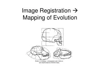
Image Registration Mapping of Evolution
370 likes | 488 Vues
This document explores the fundamentals of image registration, focusing on spatial and intensity transformations. It outlines various registration goals and methodologies, including rigid, affine, projective, and polynomial transformations. The necessity of known correspondences is highlighted, emphasizing methods such as correlation, Fourier techniques, and point mapping. The document further discusses feature spaces, similarity metrics, and robust multi-sensor image alignment, all aimed at achieving precise image matching and enhancing image quality through local correlation strategies.

Image Registration Mapping of Evolution
E N D
Presentation Transcript
Registration Goals I2(x,y)=g(I1(f(x,y))f() – 2D spatial transformationg() – 1D intensity transformation • Assume the correspondences are known • Find such f() and g() such that the images are best matched
Spatial Transformations • Rigid • Affine • Projective • Perspective • Global Polynomial • Spline
Rigid Transformation • Rotation(R) • Translation(t) • Similarity(scale)
Affine Transformation • Rotation • Translation • Scale • Shear No more preservation of lengths and angles Parallel lines are preserved
Perspective Transformation(2) • (xo,yo,zo) world coordinates • (xi,yi) image coordinates • Flat plane tilted with respect to the camera requires Projective Transformation
Projective Transformation • (xp,yp) Plane Coordinates • (xi,yi) Image Coordinates • amn coefficients from the equations of the scene and the image planes
Complex Transformations Global Polynomial Transformation(splines)
Methods of Registration • Correlation • Fourier • Point Mapping
Correlation Based Techniques Given a two images T & I, 2D normalized correlation function measures the similarity for each translation in an image patch Correlation must be normalized to avoid contributions from local image intensities.
Correlation Theorem • Fourier transform of the correlation of two images is the product of the Fourier transform of one image and the complex conjugate of the Fourier transform of the other.
Fourier Transform Based Methods • Phase-Correlation • Cross power spectrum • Power cepstrum All Fourier based methods are very efficient, only only work in cases of rigid transformation
Point Mapping Registration • Control Points • Point Mapping with Feedback • Global Polynomial
Control Points Intrinsic Markers within the Image Extrinsic Manually or Automatically selected After the control points have been determined, cross correlation, convex hull edges and other common methods are used to register the sets of control points
Point mapping with Feedback • Clustering example: determine the optimal spatial transformation between images by an evaluation of all possible pairs of feature matches. • Initialize a point in cluster space for each transformation • Use the transformation that is closest to the best cluster • Too many points, thus use a subset
Global Polynomial Transformation(1) • Use a set of patched points to generate a single optimal transformation • Bi-Variate transformation: (x,y) – reference image (u,v) – working image
Global Polynomial Transformation(2) • When is polynomial transformation bad? • Splines approximate polynomial transformations(B-spline, TP-spline)
Characteristics of Registration Methods • Feature Space • Similarity Metrics • Search Strategy
Robust Multi-Sensor Image Alignment Irani & Anandan Direct Method(vs. Feature Based)
Multi Sensor Images EO IR Find features Loss of important information Original Image (Intensity Map) Assume global statistical correlation Often violated
Multi Sensor Image Representation(1) • Same Modality Camera Sensors enough correlated structure at all resolution levels • Different Modality Camera Sensors primary correlation only in high resolution levels
Multi Sensor Image Representation(2) Goal: Suppress non-common information & capture the common scene details Solution: High pass energy images
Laplacian Energy Images • Apply the Laplacian high pass filter to the original images • Square the results NO contrast reversal BUT The Laplacian is directionally invariant
Directional Derivative Energy Images • Filter with Gaussian • Apply directional derivative filter to the original image in 4 directions • Square the resultant images
Alignment Algorithm • Do not assume global correlation, use only local correlation information • Use Normalized Correlation as a similarity measure • Thus, no assumptions about the original data
Behavior of Normalized Correlation with Energy Images • NC=1 Two images are linearly related • NC<1(high) Two images are not linearly related, yet local fluctuations are low • NC<1(low)≈0 Incorrect displacements
Global Alignment with Local Correlation(1) a, b – original images {ai,bi} – directional derivatives (i=1..4) p=(p1…p6)Taffine (u,v) – shift from one image to another Si(x,y)(u,v) – correlation surface at a pixel(x,y)
Global Alignment with Local Correlation(2) Goal: Find the parametric transformation p, which maximizes the sum of all normalized correlation values. global similarity M(p)
Solving for M(p) Newton’s method is used to solve for M(p) • The quadratic approximation of M around p is obtained by combining the quadratic approximations of each of the local correlation surfaces S around local displacement.
Steps of the Algorithm • Construct a Laplacian resolution pyramid • Compute a local normalized-correlation surface around a given displacement • Compute the parametric refinement • Update p • Start over(process terminates at the highest resolution level of the last image)
Outlier Rejection Due to the different modalities of the sensors, the number of outliers may be very large • Accept pixels based on concavity of the correlation surface • Weigh the contribution of a pixel by det|H(u)|
Results EO image IR image Composite before Alignment Composite after Alignment IR image
Acknowledgements • I would like to thank Compaq for making awful computers • Professor Belongie for reviewing the slides