Download
1 / 43
540 likes | 1.24k Vues
Building Envelope Energy Audit. Building envelope: Consists of elements of a building that enclose conditioned spaces Thermal energy exchanges between the building envelope and outside environment Information needed for building envelope EA: Building characteristics and construction

E N D
Building envelope: • Consists of elements of a building that enclose conditioned spaces • Thermal energy exchanges between the building envelope and outside environment • Information needed for building envelope EA: • Building characteristics and construction • Window and door characteristics; • Insulation status • Building characteristics and construction • Building orientation • Glazing orientation and cooling zones • Building floor, wall, and ceiling construction details
Window and door characteristics • Frame type • Window and door area • Estimated % of gross wall area • Single or double glazing, u-value • Glazing coatings • Operable windows • Alignment of operable windows • Cracked or broken panes • Weather-stripping condition • Daylighting • Skylights • Insulation status • Type, thickness and location of the existing insulation • Age and condition of the roof • Colour of the roof membrane • Damaged or wet insulation • Insulation voids
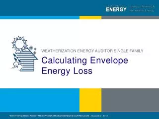
1. Building dynamics Heat gain of a building
2. Building characteristics and construction 2.1 Infiltration • Infiltration/Leakage of air: caused by cracks, openings around windows and doors and access openings; is a kind of uncontrollable ventilation • Heat exchange caused by infiltration rate: Q1=1.08 * cfm * ΔT, where cfm: ventilation/infiltration rate, in cubic feet per minute; ΔT: allowable heat rise; Q: heat removal, in Btu/hr. • Infiltration causes serious heat loss as the following figure shows:
Assumptions • The previous figure is based upon a six-month heating season (mid-October to mid-April) and an average wind velocity of 4 mph. • It is assumed that the heated building is maintained at 65°F. It can be adjust for different conditions: Q=Q1 * (d/5) * |65 – T|/13, with Q1: heat loss calculated by the above figure; d: the days of operation; T: the average ambient temperature in °F during the heating season; Q: adjusted heat loss
Strategy to prevent heat loss of infiltration: install vinyl strips: 90% efficient to prevent heat loss
Example: An energy audit of a building indicated that the warehouse is maintained at 65°F during winter and has three 10 ft × 10 ft forklift doors. The warehouse is used 24 hours, 6 days per week, and the doors are open 8 hours per day. The average ambient temperature during the heating season is 48°F. Comment on adding vinyl strips (installed cost $2,000) which are 90% efficient, given the cost of heating fuel is $4/million Btu with a boiler efficiency of 0.65. • Analysis: From the previous figure, Door area: 100ft2 Q1 = 600 × 106 Btu/Year Q=Q1* (d/5) * |65 – T|/13, Therefore Q = 600 × 106 × 6/5 × (65 – 48)/13 = 941 million BTU/year per door • Total fuel cost saving= 3 × 941 × 0.9 × $4/million BTU/65 = $15,635 • Payback =2000/15635=0.128 year=1.54 months
* All values are based on the wind blowing directly at the wind or door. When the prevailing wind direction is oblique to the windows or doors, multiply the above values by 0.60 and use the total window and door area on the windward side(s). † Based on a wind velocity at 15 mph. For design wind velocities different from the base, multiply the table values by the ratio of velocities.
Fig. 6-6 Compute energy saving based on reducing infiltration rates in heating seasons, use figure :
Fig. 6-6 is the yearly energy used. • The energy used per year was determined by: BTU/year = (1000 cfm) (Degree Days/year) (24 hr/day 1.08), where 1.08 is a factor which incorporates specific heat, specific volume, and time.
72 Degree 50 40 Fig. 6-7 Cooling 10 50% 60% 70%
Example: An energy audit survey indicates 300 windows, poorly fitted wood sash, in a building which is not weather-stripped. Comment on the savings for weather-stripping given the following: Data: Window size 54" × 96" Degree-days = 8,000 Cost of heating = $4/106 Btu One-half the windows face the wind at any one time Wet-Bulb Degree-hours = 2,000 greater than 66°F Wind velocity summer 10 mph Refrigeration consumption = .8 kW/Ton-Hr Electric rate = 5¢ kWh Hours of operation = 72 Indoor temperature winter 68°F RH summer 50% Boiler efficiency = .65
ANALYSIS Table given in cfm/ft2. Therefore, cfm=n*A*factor • Areas of windows= (54/12) × (96/12) = 36 ft2per window • Coefficients from Table 6-1 • With No Weather-stripping 1.52 • With Weather-stripping .47 • Infiltration before = 36 × 300/2 × 1.52 = 8208 cfm • Infiltration after weather-stripping = 36 × 300/2 × .47 = 2538 cfm • Savings with weather-stripping = 8208 – 2538 = 5670 cfm • From Figure 6-6, Q = 100 × 106Btu/Year/1000 cfm • Savings during winter = 5.67 × 100 × 106× $4/106/0.65 = $3489 • From Figure 6-7, Q = 10 × 106Btu/Year/1000 cfm • Savings during summer (at 10 mph wind velocity) • Savings summer = 5.67 × 10 × 106/12,000 × .8 ×.05 × 10/15 = $125.00 • Total savings = $3614 per year
2.2 Reducing Infiltration • weather-stripping • Vertical shafts, such as stairwells, should be isolated as illustrated • in Figure 6-8 (right side). Always check with fire codes before modifying building
Poor quality outdoor air dampers are another source of excess infiltration. Replacement with good quality opposed-blade dampers will reduce infiltration losses. (See Figure 6-9 in the right side)
Check exhaust hoods: Large open hoods are usually required to maintain a satisfactory capture velocity to remove fumes, smoke, etc. • Minimum capture velocity to remove contaminants. • Reducing exhaust air by fitting new baffles inside existing hood. (See Figure 6-10 in the next page.) • Installing a separate make-up air system for hoods: it consists of a fan drawing in outdoor air and passing through a heating coil to temper air.
3. HEAT FLOW DUE TO CONDUCTION • When a temperature gradient exists on either side of a wall, a flow of heat from hot side to cold side occurs and it is defined by Q = k/d • A • ΔT , U=k/d= 1/R Where: • Q is the rate of flow BTU • d is the thickness of the material in inches • A is the area of the wall, ft’ • ΔT is the temperature difference, °F • U is the conductance of the material-Btu/hr/sqft/F • k is the conductivity of the material BTU/inch2F • R is the resistance of the material. Note: insulation will increase R, and thus reduce heat flow
4. HEAT FLOW DUE TO RADIATION • Radiation is the transfer of radiant energy from a source to a receiver: Q = ε σ A T4 where: • Q = rate of heat, flow by radiation, Btu/hr • e = emissivity of a body, which is defined as the rate of energy radiated by the actual body. • ε = 1 for a block body. • σ = Stephen Boltzman’s Constant, 1.71 × 10⁻⁹ Btu/ft2 • hr • T4 • A = surface area of body in square feet. NB: • Radiant energy flow through roofs and glass should be investigated since it can significantly increase the heat gain of the building.
5. Audit of roofs • A dark covered roof will reduce the heat loss during the winter but increases the heat gain in the summer. • To reduce the HVAC load the U-Factor of the roof is increased by adding insulation. • Estimates of savings can be made by using Figures 6-13, 6-14, and 6-15. • For cooling load considerations the colour of the roof is important.
Figure 6-16. Recommended Insulation Conductance Values for Roofs and Walls
6. GLASS AUDIT 6.1 Conduction Considerations • Glass traditionally has poor conductance qualities and accounts for significant heat gains due to radiant energy • To decrease losses due to conductance either the glass needs to be replaced, modified, or an external thermal blanket added
6.2 SOLAR RADIATION CONSIDERATIONS • In addition to heat flow due to conduction, a significant heat flow occurs through glass due to the sun’s radiant energy. • To reduce solar loads, use devices: • Roller shades (least expensive) • Reflective polyester film • Venetian blinds • Vertical louver blinds • External louvered screens • Tinted or reflective glass (most expensive)
7. Window Treatment 7.1 Solar control • Solar Control Films: A range of tinted and reflective polyester films are available to adhere to inner window surfaces to provide solar control for existing clear glazing. • Most films are adhered with pre-coated pressure-sensitive adhesives. Reflective films will reduce winter U values by about 20%.
Fibre Glass Solar Control Screens: • Motorized Window Shading System: • Exterior Sun Control Louvers: • External Venetian Blinds: • Adjustable Louvered Windows
7.2 Thermal barriers: • Multilayer, Roll-Up Insulating Window Shade: • create a series of dead air spaces.
Louvered Metal Solar Screens • Solar screen consists of an array of tiny louvers which are formed from a sheet of thin aluminium. The louvered aluminium sheet is then installed in conventional screen frames
Operable External Louver Blinds • Solar control louver blinds, mounted on the building exterior, can be controlled manually or automatically by sun and wind sensors.
Louvered Metal Solar Screens • Solar screen consists of an array of tiny fixed horizontal louvers which are woven in place. • Installed screens have considerable wind and impact resistance.
7.3 PASSIVE SOLAR BUILDING DESIGNS • A passive solar system is defined as one in which thermal energy flows by natural means. • Examples of solar building design: • Solar greenhouses: can produce 60-100% of heating and cooling requirements. • Underground buildings: provide year-round temperature requirements. • Enhanced natural ventilation through solar chimneys • To study how the building reacts to loads, its storage effect, etc. computer simulations are often used. (e.g. PEGFIX, PEGFLOAT)
Circulation • Make-up air handler: Air from outside • Blower/recirculator/destratifier: air from inside (terminal units)
Example: Comment on reducing the stratified air temperature from 90°F to 75°F during the heating season, with U = 0.1, Area = 20,000 square feet, and assume an outside temperature of 15°F and exhaust cfm of 20,000. ANALYSIS: • A handy formula to relate heat loss from cfm exhausts is: Q = 1.08 Btu Min./Hr.ft3 × F × ΔT • Before change: Qconduction = U AΔT = .1 × 20,000 × 75 = 150,000 Btu/H Qcfm = 1.08 × 20,000 × 75 = 1,620,000 Btu/H QT = 1,770,000 Btu/H • After change in stratification temperature: Qc = 0.1 × 20,000 × 60 = 120,000 Btu/h Qcfm = 1.08 × 20,000 × 60 = 1,296,000 Btu/h QT = 1,416,000 Btu/h % savings – heating season = 100 – 1,416,000/1,770,000 × 100 = 20% × 100 = 20%