Download

1 / 53
530 likes | 695 Vues
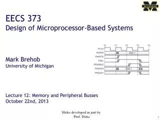
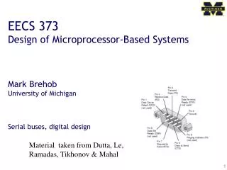
EECS 373 Design of Microprocessor-Based Systems Mark Brehob University of Michigan Serial buses, digital design. Material taken from Dutta , Le, Ramadas , Tikhonov & Mahal. Topic talks. The group on 11/12 may be on 11/7 depending on guest speaker availability.

E N D
EECS 373 Design of Microprocessor-Based Systems Mark Brehob University of Michigan Serial buses, digital design Material taken from Dutta, Le, Ramadas, Tikhonov & Mahal
Topic talks The group on 11/12 may be on 11/7 depending on guest speaker availability
Meeting tonight—Project group formation • 6:30pm in 1500 EECS • Come with ideas and a willingness to talk about them. • Groups of 3 or 4 preferred. • Groups of 2 allowed but discouraged.
Agenda • Serial Buses, • UART (again) • SPI • I2C • Glitches • Asynchronous resets and glitches • Design rules • Set-up and hold time. • Review • Dealing with external inputs • Design rules
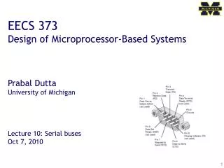
External memory attaches to the processor via the external memory controller and bus Atmel SAM3U
UART • Universal Asynchronous Receiver/Transmitter • a type of "asynchronous receiver/transmitter", a piece of computer hardware that translates data between parallel and serial forms. • UARTs are commonly used in conjunction with communication standards such as EIA, RS-232, RS-422 or RS-485. • The universal designation indicates that the data format and transmission speeds are configurable and that the actual electric signaling levels and methods (such as differential signaling etc.) typically are handled by a special driver circuit external to the UART. Most of the UART stuff (including images) Taken from Wikipedia!
Protocol • Each character is sent as • a logic lowstart bit • a configurable number of data bits (usually 7 or 8, sometimes 5) • an optional parity bit • one or more logic high stop bits.
Variations and fun times • UART is actually a generic term that includes a large number of different devices/standards. • RS-232 is a standard that specifies • “electrical characteristics and timing of signals, the meaning of signals, and the physical size and pin out of connectors.
Signals (only most common) • The RXD signal of a UART is the signal receiving the data. This will be an input and is usually connected to the TXD line of the downstream device. • The TXD signal of a UART is the signal transmitting the data. This will be an output and is usually connected to the RXD line of the downstream device. • The RTS# (Ready to Send) signal of a UART is used to indicate to the downstream device that the device is ready to receive data. This will be an output and is usually connected to the CTS# line of the downstream device. • The CTS# (Clear to Send) signal of a UART is used by the downstream device to identify that it is OK to transmit data to the upsteam device. This will be an input and is usually connected to the RTS# line of the upstream device.
DB9 stuff • DTE vs DCE • Pinout of a DCE? • Common ground? • Noise effects? Wiring a DTE device to a DCE device for communication is easy. The pins are a one-to-one connection, meaning all wires go from pin x to pin x. A straight through cable is commonly used for this application. In contrast, wiring two DTE devices together requires crossing the transmit and receive wires. This cable is known as a null modem or crossover cable.
Introduction • What is it? • Basic Serial Peripheral Interface (SPI) • Capabilities • Protocol • Pro / Cons and Competitor • Uses • Conclusion Serial Peripheral Interface http://upload.wikimedia.org/wikipedia/commons/thumb/e/ed/ SPI_single_slave.svg/350px-SPI_single_slave.svg.png
What is SPI? • Serial Bus protocol • Fast, Easy to use, Simple • Everyone supports it
SPI Basics • A communication protocol using 4 wires • Also known as a 4 wire bus • Used to communicate across small distances • Multiple Slaves, Single Master • Synchronized
Capabilities of SPI • Always Full Duplex • Communicating in two directions at the same time • Transmission need not be meaningful • Multiple Mbps transmission speed • Transfers data in 4 to 16 bit characters • Multiple slaves • Daisy-chaining possible
Protocol • Wires: • Master Out Slave In (MOSI) • Master In Slave Out (MISO) • System Clock (SCLK) • Slave Select 1…N • Master Set Slave Select low • Master Generates Clock • Shift registers shift in and out data
Wires in Detail • MOSI – Carries data out of Master to Slave • MISO – Carries data from Slave to Master • Both signals happen for every transmission • SS_BAR – Unique line to select a slave • SCLK – Master produced clock to synchronize data transfer
Shifting Protocol Master shifts out data to Slave, and shift in data from Slave http://upload.wikimedia.org/wikipedia/commons/thumb/b/bb/SPI_8-bit_circular_transfer.svg/400px-SPI_8-bit_circular_transfer.svg.png
Diagram Some wires have been renamed Master and multiple daisy-chained slaves http://www.maxim-ic.com/appnotes.cfm/an_pk/3947 Master and multiple independent slaves http://upload.wikimedia.org/wikipedia/commons/thumb/f/fc/SPI_three_slaves.svg/350px-SPI_three_slaves.svg.png
Clock Phase (Advanced) • Two phases and two polarities of clock • Four modes • Master and selected slave must be in same mode • Master must change polarity and phase to communicate with slaves of different numbers
Timing Diagram Timing Diagram – Showing Clock polarities and phases http://www.maxim-ic.com.cn/images/appnotes/3078/3078Fig02.gif
Pros and Cons Pros: • Fast and easy • Fast for point-to-point connections • Easily allows streaming/Constant data inflow • No addressing/Simple to implement • Everyone supports it Cons: • SS makes multiple slaves very complicated • No acknowledgement ability • No inherent arbitration • No flow control
Uses • Some Serial Encoders/Decoders, Converters, Serial LCDs, Sensors, etc. • Pre-SPI serial devices
Conclusion • SPI – 4 wire serial bus protocol • MOSI MISO SS SCLK wires • Full duplex • Multiple slaves, One master • Best for point-to-point streaming data • Easily Supported
EECS 270++ Our digital logic class, EECS 270, does a great job dealing with logic basics. But it only has so much time and has a wide variety of follow-on classes (373, 470, 478) to support. Today we’ll spend time reviewing some 270 material, introducing some new material, and providing design guidelines. We’ll then wrap it working on a rather difficult digital design problem involving interfacing.
Agenda • Serial Buses • UART (again) • SPI • I2C • Glitches • Asynchronous resets and glitches • Design rules • Set-up and hold time. • Review • Dealing with external inputs • Design rules
Glitches • Combinational logic can glitch • What is a glitch? • How do we normally deal with it? • Where can it hurt us?
Timing • Assuming the XOR gates have a delay of 0.2ns while AND and OR gates have a delay of 0.1ns • What is the worst case propagation delay for this circuit? x y z Full adder (from Wikipedia)
Glitches Consider the adjacent circuit diagram. Assuming the XOR gates have a delay of 0.2ns while AND and OR gates have a delay of 0.1ns, fill in the following chart. Full adder (from Wikipedia) x y z Only selected causality arrows shown…
Glitching: a summary • When input(s) change, the output can be wrong for a time. However, that time is bound. • And more so, the output can change during this “computation time” even if the output ends up where it started!
Effect of Glitches • Think back to EECS 370. • Why don’t glitches cause errors? • The trick is that the inputs all change at the same time • In this case, the ID/EX registers all change some time shortly after the rising edge of the clock. • And we’ve chosen the clock period such that the next edge doesn’t happen until the combinational logic has stopped glitching. • In fact, we use the worst-case combinational logic delay in the whole system when determining the clock period!
So, how can glitches hurt us? • There are a handful of places: • Asynchronous resets • If you’ve got a flip-flop that has an asynchronous reset (or “preset”) you need to be sure the input can’t glitch. • That pretty much means you need a flip-flop driving the input (which means you probably should have used a sync. reset!) • Clocks • If you are using combinational logic to drive a clock, you are likely going to get extra clock edges. Traditionally, CLR is used to indicate async reset. “R” or “reset” for sync. reset. If clk is high and cond glitches, you get extra edges!
Design rules • Thou shall Not use asynchronous resets • Thou shall not drive a clock with anything other than a clock or directly off of a flip-flop’s output X X
Really? • I mean people use asynchronous resets and clock gating! • Yep. And people use gotoin C programs. • Sometimes they are the right thing. • But you have to think really hard about them to insure that they won’t cause you problems. • Our “simple” bus usedcombinational logic forthe clock • Works because REQ goeslow only after everythingelse has stopped switching • So no glitch. • Not fun to reason about… • Avoid unless you must • Then think really carefully.
Agenda • Serial Buses, • UART (again) • SPI • I2C • Glitches • Asynchronous resets and glitches • Design rules • Set-up and hold time. • Review • Dealing with external inputs • Design rules
Setup and hold time • The idea is simple. • When the clock is changingif the data is also changing itis hard to tell what the datais. • Hardware can’t always tell • And you can get meta-stable behavior too (very unlikely but…) • So we have a “guard band” around the clock rising time during which we don’t allow the data to change. • See diagram. We call the time before the clock-edge “setup time” and the time after “hold time”
So what happens if we violate set-up or hold time? • Often just get one of the two values. • And that often is just fine. • Consider getting a button press from the user. • If the button gets pressed at the same time as the clock edge, we might see the button now or next clock. • Either is generally fine when it comes to human input. • But bad things could happen. • The flip-flop’s output might not settle out to a “0” or a “1” • That could cause latter devices to mess up. • More likely, if that input is going to two places, one might see a “0” the other a “1”.