Download
1 / 12
120 likes | 219 Vues
Study on smoke extraction system in tunnel using SEVS, focusing on air flow rates, velocities, and performance with different scenarios. Results show higher velocities with two extractors working.

E N D
PS Ventilation - Smoke extraction - 2013-04-17
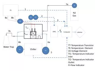
Air inlets Boundary conditions / assumptions: • Only SEVS system • Extraction in TR3-TR8, 30 000 m³/h each • Air inlets in the galleries corresponding to TR1 and TR2 • Case with open doors in the center (area 2,5m²) • Two scenarios – only extractor 3 is working and only extractors 3 and 4 are working Smokeextractors Center 2013-04-17
Boundary conditions / assumptions: • Extraction: velocity ~5m/s, area 1,7m² (velocity inlets) • Inlets: TR1: 3,0m X 3,4 m; TR2: 3,0 m X 3,4 m (pressure inlets), central – velocity inlet (1,3m X 0,55m) or pressure inlet 1,25m X 2,0m • Tunnel leak tight 2013-04-17
Results 2013-04-17
Conventions + + + + • “r45” means flow rate in the tunnel between the technical room 4 and 5. • Flow rate in tunnels (r12, r23, etc.) is positive when counter-clockwise. • Flow rate in galleries is positive when moving radially from the ring center to the outside. 2013-04-17
Velocity in the tunnel (m/s) Extractor 3 Extractors 3 + 4 0.27 0.11 0.12 0.23 0.13 0.06 0.13 0.005 0.05 0.14 0.14 0.007 0.11 0.23 0.006 0.007 0.12 0.21 0.06 0.43 0.21 0.23 0.46 0.13 0.07 0.03 0.51 0.26 0.23 0.11 0.44 0.87 0.24 0.11 0.07 0.04 2013-04-17
Air flow rates in the tunnel 2013-04-17
Air flow rates in the galleries • Even galleries have smaller cross section • The flow rate values are taken in the center of the gallery (50 meter from the center of the ring) 2013-04-17
Velocity in the galleries 2013-04-17
Extractors 3 + 4 Extractor 3 2013-04-17
Conclusions • Simulations are done with an opening in the central room – this solution was found as the best for the flow in the galleries • The results are as expected: the air is going from both inlets and goes to the right and to the left to finally reach te extractors • The air flow in some galleries (especially 6 and 7) is really low – it is even hard to jugde in which direction the air will go • Velocities in the tunnel are higher when two extractors are working 2013-04-17
END 2013-04-17