Raster Graphics Hardware
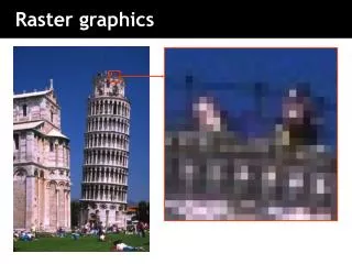
Raster Graphics Hardware. EXAMPLE RASTER GRAPHICS ARCHITECTURE. RASTER: A rectangular array of points or dots. PIXEL (Pel): One dot or picture element of the raster SCAN LINE: A row of pixels. BASIC DEFINITIONS.

Raster Graphics Hardware
E N D
Presentation Transcript
RASTER: A rectangular array of points or dots. PIXEL (Pel): One dot or picture element of the raster SCAN LINE: A row of pixels BASIC DEFINITIONS Video raster devices display an image by sequentially drawing out the pixels of the scan lines that form the raster.
Pixel - The most basic addressable image element in a screen CRT - Color triad (RGB phosphor dots) LCD - Single color element Screen Resolution - measure of number of pixels on a screen (m by n) m - Horizontal screen resolution n - Vertical screen resolution Pixels
There are no commercially available small pixel technologies that can individually change color. Color is encoded by placing different-colored pixels adjacent to each other. Field sequential color uses red, blue and green liquid crystal shutters to change color in front of a monochrome screen. Color
Raster Displays • Cathode Ray Tubes (CRTs), most “tube” monitors you see. Very common, but big and bulky. • Liquid Crystal Displays (LCDs) • - there are two types: • 1) transmissive (Shine light through the image-forming element, e.g. laptops, those snazzy new flat panel monitors) • 2) reflective (Bounce light off the image-forming element e.g. wrist watches).
•Contains a filament that, when heated, emits a stream of electrons. •Electrons are focused with an electromagnet into a sharp beam and directed to a specific point of the face of the picture tube. •The front surface of the picture tube is coated with small phosphor dots. •When the beam hits a phosphor dot it glows with a brightness proportional to the strength of the beam and how often it is excited by the beam. Electron Gun
CRT Phosphor Screen • The screen is coated with phosphor, 3 colors for a color monitor, 1 for monochrome. • For a color monitor, three guns light up red, green, or blue phosphors. • Intensity is controlled by the amount of time at a specific phosphor location.
FLUORESCENCE - Light emitted while the phosphor is being struck by electrons. PHOSPHORESCENCE - Light given off once the electron beam is removed. PERSISTENCE - Is the time from the removal of excitation to the moment when phosphorescence has decayed to 10% of the initial light output. Color CRT •Red, Green and Blue electron guns. •Screen coated with phosphor triads. •Each triad is composed of a red, blue and green phosphor dot. •Typically 2.3 to 2.5 triads per pixel.
Frame: The image to be scanned out on the CRT. •Some minimum number of frames must be displayed each second to eliminate flicker in the image. Scanning An Image CRITICAL FUSION FREQUENCY •Typically 60 times per second for raster displays. •Varies with intensity, individuals, phosphor persistence, room lighting.
VERTICAL SYNC PULSE — Signals the start of the next field. VERTICAL RETRACE — Time needed to get from the bottom of the current field to the top of the next field. HORIZONTAL SYNC PULSE — Signals the start of the new scan line. HORIZONTAL RETRACE — Time needed to get from the end of the current scan line to the start of the next scan line. Scanning
•Scan frame 30 times per second •To reduce flicker, divide frame into two fields—one consisting of the even scan lines and the other of the odd scan lines. •Even and odd fields are scanned out alternately to produce an interlaced image. Interlaced Scanning Image from http://www.anchorbaytech.com/_media/images/support/interlaced-scan.jpg
NTSC - 525x480, 30f/s, interlaced PAL - 625x480, 25f/s, interlaced VGA - 640x480, 60f/s, noninterlaced SVGA – 800x600, 60f/s noninterlaced RGB - 3 independent video signals and synchronization signal, vary in resolution and refresh rate Time-multiplexed color - R,G,B one after another on a single signal, vary in resolution and refresh rate Video Formats
Liquid Crystal Displays (LCDs) • Also divided into pixels, but without an electron gun firing at a screen, LCDs have cells that either allow light to flow through, or block it.
Liquid crystal displays use small flat chips which change their transparency properties when a voltage is applied. LCD elements are arranged in an n x m array call the LCD matrix Level of voltage controls gray levels. LCDs elements do not emit light, use backlights behind the LCD matrix Liquid Crystal Displays (LCDs)
Color is obtained by placing filters in front of each LCD element Usually black space between pixels to separate the filters. Because of the physical nature of the LCD matrix, it is difficult to make the individual LCD pixels very small. Image quality dependent on viewing angle. Liquid Crystal Displays (LCDs)
LCD resolution is often quoted as number of color elements not number of RGB triads. LCDs (cont.) Example: 320 horizontal by 240 vertical elements = 76,800 elements Equivalent to 76,800/3 = 25,500 RGB pixels "Pixel Resolution" is 185 by 139 (320/1.73, 240/1.73)
Passive LCD screens Cycle through each element of the LCD matrix applying the voltage required for that element. Once aligned with the electric field the molecules in the LCD will hold their alignment for a short time Active LCD screens Each element contains a small transistor that maintains the voltage until the next refresh cycle. Higher contrast and much faster response than passive LCD LCDs (cont.)
Flat Lightweight Low power consumption Advantages of LCDs
Strong electrical fields and high voltage Very good resolution Heavy, not flat CRTs (cont.)
A frame buffer may be thought of as computer memory organized as a two-dimensional array with each (x,y) addressable location corresponding to one pixel. Bit Planes or Bit Depth is the number of bits corresponding to each pixel. A typical frame buffer resolution might be 640 x 480 x 8 1280 x 1024 x 8 1280 x 1024 x 24 Frame Buffers
True Color Display24 bitplanes, 8 bits per color gun. 224 = 16,777,216
Extends the number of colors that can be displayed by a given number of bit-planes. y RED max GREEN 255 BLUE 1 1 0 0 y 0 67 Pixel displayed 0 1 1001 1010 0001 at x', y' 0 67 100110100001 B R G Pixel in bit map 0 at x', y' 0 x x 0 max Bit map Look-up table Display Color Map Look-Up Tables
Pseudo Color: 28 x 24 Color Map LUT Could be used to define 256 shades of green or 64 shades each of red, blue, green and white, etc.
Examples of Pseudo Color Application Image from www.mirametrics.com/brief_contour.htm Image from hinode.nao.ac.jp/news_e/20061127_press_e Image from www.catenary.com/howto/pseudo.html
Specialized hardware to assist in scan converting output primitives into the frame buffer. Fundamental difference among display systems is how much the display processor does versus how much must be done by the graphics subroutine package executing on the general-purpose CPU. Display Processor Also called either a Graphics Controller or Display CoProcessor or Graphics Accelerator or Video Card
Cycles through the frame buffer, one scan line at a time. Contents of the memory are used to control the CRT's beam intensity or color. Video Controller
Projection Displays • Use bright CRT or LCD screens to generate an image which is sent through an optical system to focus on a (usually) large screen. • Full color obtained by having separate monochromatic projector for each of the R,G,& B color channels
Basic Projector Designs(Images from Phillips Research) Reflective Projection System Transmittive Projection System
Very large screens can provide large field of view and can be seen by several people simultaneously. Image quality can be fuzzy and somewhat dimmer than conventional displays. Sensitive to ambient light. Delicate optical alignment. Less eye strain Very immersive Very expensive Advantages/Disadvantagesof Projection Display
Head-Mounted Displays (HMDs) The display and a position tracker are attached to the user’s head Head-Tracked Displays (HTDs) Display is stationary, tracker tracks the user’s head relative to the display. Example: CAVE, Workbench, Stereo monitor Displays in Virtual Reality
Image Quality Issues • Screen resolution • Color • Blank space between the pixels • Intentional image degradation • Brightness • Contrast • Refresh rate • Sensitivity of display to viewing angle
Locator Devices: to indicate a position and/or orientation e.g. Tablet, Mouse, Trackball, Joystick, Touch Panel, Light Pen Keyboard devices: to input a character string e.g. Alphanumeric keyboard Scanner Image Scanners, e.g. Flatbed, etc What type of data is returned? Bitmap Laser Scanners, e.g. Deltasphere Emits a laser and does time of flight. Returns 3D point Input Devices