Download
1 / 25
260 likes | 297 Vues
TRANSVERSE RESISTIVE-WALL IMPEDANCE FROM ZOTTER2005’S THEORY. Elias Métral ( 25 + 5 min, 25 slides ). “Low-frequency” regime. Introduction and motivation Numerical applications for a LHC collimator (vs. Burov-Lebedev2002 and Bane1991)

E N D
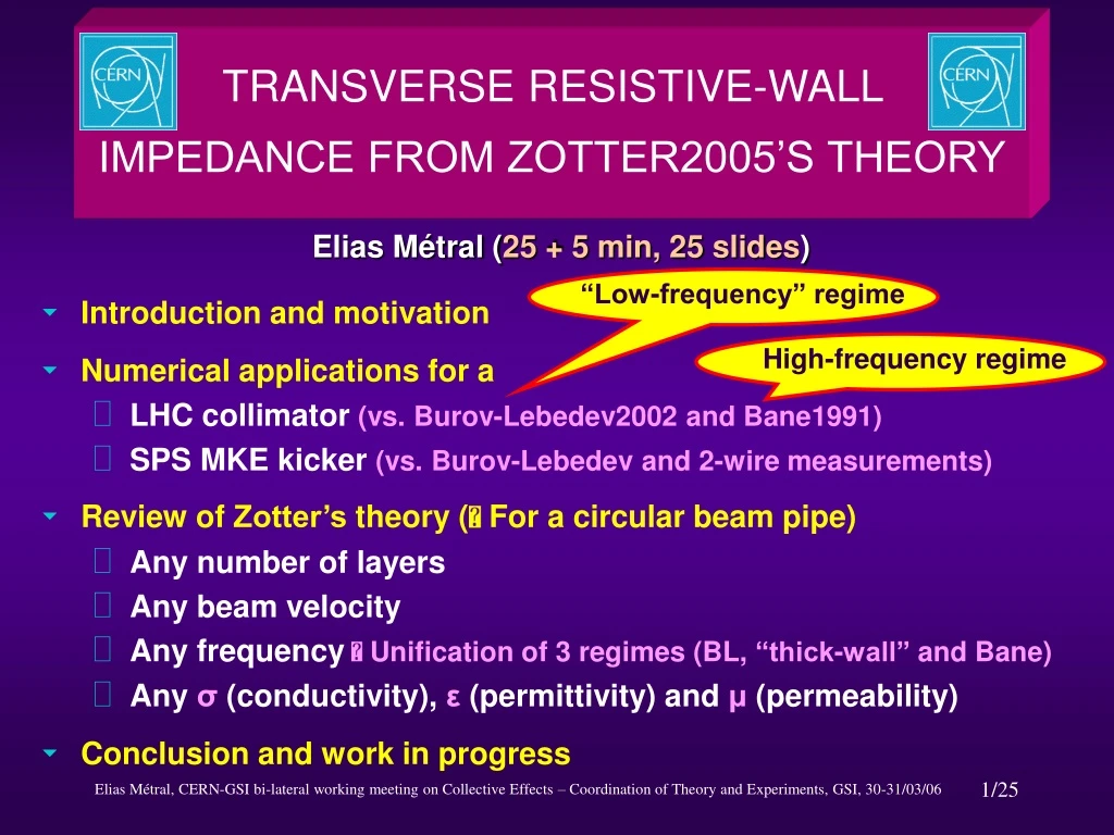
TRANSVERSE RESISTIVE-WALL IMPEDANCE FROM ZOTTER2005’S THEORY Elias Métral (25 + 5 min, 25 slides) “Low-frequency” regime • Introduction and motivation • Numerical applications for a • LHC collimator (vs. Burov-Lebedev2002 and Bane1991) • SPS MKE kicker (vs. Burov-Lebedev and 2-wire measurements) • Review of Zotter’s theory ( For a circular beam pipe) • Any number of layers • Any beam velocity • Any frequency Unification of 3 regimes (BL, “thick-wall” and Bane) • Any σ (conductivity), ε (permittivity) and μ (permeability) • Conclusion and work in progress High-frequency regime
INTRODUCTION AND MOTIVATION (1/2) THE MOTIVATION: THE LHC GRAPHITE COLLIMATORS • First unstable betatron line • Skin depth for graphite (ρ = 10 μΩm) • Collimator thickness One could think that the classical “thick-wall” formula would be about right
INTRODUCTION AND MOTIVATION (2/2) • In fact it is not The resistive impedance is ~ 2 orders of magnitude lower at ~ 8 kHz ! A new physical regime was revealed by the LHC collimators Usualregime : New regime :
COMPARISON ZOTTER2005-BUROV&LEBEDEV2002 N.A. FOR A LHC COLLIMATOR (1/4) Classical thick-wall BL’s results (real and imag. parts) in black: dots without and lines with copper coating
N.A. FOR A LHC COLLIMATOR (2/4) GLOBAL PLOT FROM ZOTTER2005 Low beam velocity case (e.g. PSB : , ) Same as Bane1991 Negative AC conductivity
REVIEW OF ZOTTER’S THEORY (1/17) • 1) Maxwell equations • In the frequency domain, all the field quantities are taken to be proportional to • Combining the conduction and displacement current terms yields with
REVIEW OF ZOTTER’S THEORY (2/17) • 2) Scalar Helmholtz equations for the longitudinal field components Using , one obtains (using the circular cylindrical coordinates r, θ, z) • The homogeneous equation can be solved by separation of variables
REVIEW OF ZOTTER’S THEORY (3/17) m is called the azimuthal mode number (m=1 for pure dipole oscillations) and k is called the wave number Reinserting the time dependence ( ), the axial motion is seen to be a wave proportional to , with phase velocity which may in general differ from the beam velocity R (r) is given by with Radial propagation constant The solutions of this differential equation are the modified Bessel functions and
REVIEW OF ZOTTER’S THEORY (4/17) • Conclusion for the homogeneous scalar Helmholtz equations • For pure dipole oscillations excited by a horizontal cosine modulation propagating along the particle beam, one can write the solutions for Hz and Ezas • Sine and cosine are interchanged for a purely vertical excitation (see source fields) • Only the solutions of the homogeneous Helmholtz equations are needed since all the regions considered are source free except the one containing the beam where the source terms have been determined separately by Gluckstern (CERN yellow report 2000-011) See slide 14 C1,2 and D1,2 are constants to be determined
REVIEW OF ZOTTER’S THEORY (5/17) • 3) Transverse field components deduced from the longitudinal ones using Maxwell equations (in a source-free region)
REVIEW OF ZOTTER’S THEORY (6/17) • 4) Source of the fields: Ring-beam distribution Infinitesimally short, annular beam of charge and radius traveling with velocity along the axis • Charge density in the frequency domain where is the horizontal dipole moment
REVIEW OF ZOTTER’S THEORY (7/17) • Longitudinal source terms (from Gluckstern) Valid for , i.e. in the vacuum between the beam and the pipe = region (1) with and will be determined by the boundary conditions at b and d
REVIEW OF ZOTTER’S THEORY (8/17) • 5) The total (i.e. resistive-wall + space charge) horizontal impedance with L the length of the resistive pipe and
REVIEW OF ZOTTER’S THEORY (9/17) • The space-charge impedance is obtained with a perfect conductor at r = b, i.e.when and , with • If and
REVIEW OF ZOTTER’S THEORY (10/17) • The resistive-wall impedance is obtained by subtracting the space-charge impedance from the total impedance Only remains to be determined (by field matching)
REVIEW OF ZOTTER’S THEORY (11/17) • 6) Field matching • At the interfaces of 2 layers (r = constant) all field strength components have to be matched, i.e. in the absence of surface charges and currents the tangential field strengths and have to be continuous • Then the radial components of the displacement and of the induction are also continuous, i.e. matching of the radial components is redundant • At a Perfect Conductor (PC) : • At a Perfect Magnet (PM) : • At r Infinity Only is permitted as diverges
REVIEW OF ZOTTER’S THEORY (12/17) • General form of the field strengths in region (p) (Ep, Gp, αp and ηp) are constants to be determined …
REVIEW OF ZOTTER’S THEORY (13/17) • 7) General 1-layer formula α2 and η2are determined by the boundary conditions at the outer chamber wall r = d
REVIEW OF ZOTTER’S THEORY (14/17) d , or PC or PM (2) Layer 1 • d • Perfect Conductor (PC) (1) Vacuum Beam a b • Perfect Magnet (PM) d
REVIEW OF ZOTTER’S THEORY (15/17) • 8) General 2-layer formula where the parameters (E2, α2) are 2 parameters out of 4 (α2, η2, E2 and G2) which have to be found by solving the matching equations at each layer boundary. The 4 unknowns are given by the following system of 4 linear equations
REVIEW OF ZOTTER’S THEORY (16/17) 1,2,3 refer to the vacuum (between the beam and the first layer), the first and second layer respectively
REVIEW OF ZOTTER’S THEORY (17/17) (3) Layer 2 e , or PC or PM (2) Layer 1 (1) Vacuum • e Beam a b d e
CONCLUSION AND WORK IN PROGRESS • Zotter2005’s formula has been compared to other approaches from Burov-Lebedev2002, Tsutsui2003 (theory and HFSS simulations) and Vos2003 (see Ref. 6 below) Similar results obtained in the new (Burov-Lebedev2002) low-frequency regime • Work in Progress • Multi-bunch or “long” bunch Wave velocity Beam velocity • Finite length of the resistive beam pipe REFERENCES [1] B. Zotter, CERN-AB-2005-043 (2005) [2] R.L. Gluckstern, CERN yellow report 2000-011 (2000) [3] E. Métral, CERN-AB-2005-084 (2005) [4] A. Burov and V. Lebedev, EPAC’02 (2002) [5] K. L.F. Bane, SLAC/AP-87 (1991) [6] F. Caspers et al., EPAC’04 (2004) [7] H. Tsutsui, LHC-PROJECT-NOTE-318 (2003) [8] L. Vos, CERN-AB-2003-005-ABP (2003) and CERN-AB-2003-093-ABP (2003)


