Introduction to Structured Light (SL) Systems and SL Based Phase Unwrapping
600 likes | 1.03k Vues
Introduction to Structured Light (SL) Systems and SL Based Phase Unwrapping. R. Garcia & A. Zakhor EECS Department UC Berkeley www-video.eecs.berkeley.edu/research. Outline. Background Structured Light Basics Phase Unwrapping Our Algorithms Results Summary.

Introduction to Structured Light (SL) Systems and SL Based Phase Unwrapping
E N D
Presentation Transcript
Introduction to Structured Light (SL) Systems and SL Based Phase Unwrapping R. Garcia & A. Zakhor EECS Department UC Berkeley www-video.eecs.berkeley.edu/research
Outline • Background • Structured Light Basics • Phase Unwrapping • Our Algorithms • Results • Summary
Determining Depth of a Scene • Many applications: • Biomedical • Industrial • Entertainment • Navigation • Methods for Determining Depth • Triangulation • Time of flight • Depth from (de)focus • Other…
Triangulation Based Depth Methods • Scene observed from multiple views • Correspondences between views solved • Must know intrinsic and extrinsic parameters for each view • Two categories • Passive: Stereo – multiple cameras • Active: Structured Light – camera with projector or other light source used I J I J Cam Projector Cam Cam [S. Narasimhan]
Traditional Stereo • Need 2 or more views of the scene • Scene texture used to identify correspondences across views • Dense stereo remains an active research area in computer vision • Algorithms and new results @ Middlebury vision • Given rectified images, triangulation is simple • Using similar triangles: [Mirmehdi]
Potential Problem with Stereo • Stereo works well on “textured” images
Potential Problem with Stereo • Stereo can fail with lack of texture ? ?
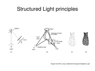
Structured Light (SL) • SL places “texture” onto the scene • Projector patterns identify each scene region • Classes of patterns • Temporal • Spatial • Other • Survey of patterns [J. Salvi et al., 2004]
Temporal Coding • Multiple frames are projected to identify scene regions • Camera pixel’s intensity change used for correspondence • Scene assumed to be static
Spatial Coding • Encodes unique information into small regions. • Fewer captures Less dense reconstruction
Spatial Coding • Recognize this?
Structured Light v. Stereo • Advantages of SL: • SL does not require a richly textured scene • Solving correspondences is not expensive • Each scene point scene receives a unique code • Advantages of Stereo: • No interference with observed scene • Only need acquisitions at one time for capture; SL often needs multiple images • Too much texture can be problematic for SL.
Outline • Background • Structured Light Basics • Phase Unwrapping • Our Algorithms • Results • Summary
Structured Light Geometry • Geometry of SL is simple • Triangulation performed by ray-plane intersection • Intrinsic and extrinsic parameters needed • Calibration matrix for camera and projector • Transformation between coordinate frame of camera and projector
Triangulation • Intrinsic and extrinsicparameters Left Cam Projector
Triangulation Left Cam Projector
SL for Dynamic Scene Capture • SL capable of capturing dynamic scenes • Want to limit capture time when capturing dynamic scenes • “One-shot” approaches require single capture • Trade-off • Fewer frames -> lower capture resolution • More frames -> more sensitive to scene motion
Overview of Phase Shifted StructuredLight (SL) Systems • Project patterns to find correspondences between camera and projector • Phase shifted sinusoidal patterns: • Fast capture: 3 shots • Simple to decode • Insensitive to blur • Used in optical metrology M periods
Example: Scene Illuminated with Phase-Shifted Sinusoids I1 I2 Unwrapped Phase Wrapped Phase I3 M periods in sinusoid Need to unwrap phase
Outline • Background • Structured Light Basics • Phase Unwrapping • Our Algorithms • Results • Summary
What is Phase Unwrapping? • Phase values usually expressed from [-π , π) • Would like to recover original continuous phase measurement
Overview of Phase Unwrapping • Unwrapping assumptions: • Single continuous object in scene • Slowly varying depth; discontinuities less than |π| • 2D phase unwrapping results in relative phase: • Need absolute phase for triangulation. Unwrapped Phase Wrapped Phase
Stereo-Assisted Phase Unwrapping D • Stereo assisted phase unwrapping [Wiese 2007]: • Results in absolute phase • Deals with depth discontinuities • System Setup: Two cameras, single projector C B A Cam 1 Cam 2 Projector
Overview of Phase Unwrapping with two Cameras [Weise et al. 2007] • To resolve the absolute phase for a camera pixel: • Determine wrapped phase for all pixels in first and second camera • Project a ray from pixel in camera 1 with wrapped phase • Project M planes from the projector corresponding to in space • Find the M intersections of the M planes with the ray in (1) in 3D space, • Project onto camera 2 • Compare the M phase values at M pixel locations in camera 2 to the and choose the closest . . . .
Stereo Phase Unwrapping [Weise et. al. 2007] Right Cam Left Cam Projector
Drawbacks of Stereo Phase Unwrapping • Must be run twice. • Possible to incorrectly assign absolute phase values to corresponding points between views. P D A C B Left Camera Right Camera
Comparison of Stereo Assisted Phase Unwrapping with Merging Stereo and 3D (x,y,t)
Temporal Inconsistencies • Consecutive phase images highly correlated • Correlated information not used during phase unwrapping • Results in inconsistent unwrapping
3D Phase Unwrapping • Multi-dimensional phase unwrapping • 2D: traditional image processing • 3D: medical imaging (i.e. MRI)
Overview of 3D (x,y,t) Phase Unwrapping • Treat consecutive phase images as volume of phase values • Edges defined between neighboring pixels • Quality assigned to each pixel Inversely proportional to spatio-temporal second derivative • Want to unwrap according to quality of edges
3D Phase Unwrapping (cont.) • Evaluate edges in a 3D volume from highest quality to lowest • Evaluating edge = unwrapping pixels connected to it • Unwrapped pixels connected in chains • Grow the chain by adding pixels/edges in x, y, and t • Chains merged together
Outline • Background • Structured Light Basics • Phase Unwrapping • Our Algorithms • Results • Summary
Consistent Stereo-Assisted Phase-UnwrappingMethods for Structured Light Systems
Merging Stereo & 3D (x,y,t) Phase Unwrapping • Goal: Solve for absolute phase offset of a chain by using stereo matching data. • Approach: use quality to find phase offset probabilistically • M periods in the sinusoidal pattern M possible phase offsets • Find offset probability for each pixel in the chain, then combine them to find phase offset for the whole chain • How to find phase offset for a pixel P: • Use phase difference between wrapped phase at P and its corresponding M projected pixels to generate likelihood of each of the M phase offset values.
Computing Phase Offset for an Entire Chain • Combine offset probabilities for each pixel in the chain to determine phase offset for the whole chain + 0π + 2π π-δ -π+δ π-2δ π-δ (a) (b) P(k2=0) P(k1=0) P(k2=0) P(k1=0) P(k2=1) P(k1=1) P(k2=1) + + : P(k1=1) : : Pixels in the same period Pixels in different periods : P(k2=M-1) P(k1=M-1) P(k2=M-1) P(k1=M-1) (a) (b)
Comparison with 3D (x,y,t) only Proposed 3D (x,y,t) Proposed algorithm avoids unwrapping low quality pixels by using stereo Handling multiple disjoint objects
Comparison with Stereo Only Stereo Only Proposed Consecutive unwrapped phase frames and their difference
Comparison of Stereo Assisted Phase Unwrapping with Merging Stereo and 3D (x,y,t)
Stereo Phase Unwrapping [Weise et. al. 2007] Right Cam Left Cam Projector
Proposed Method • Perform unwrapping w.r.t. projector pixels rather than camera pixels Right Cam Left Cam Projector
Overview of the proposed Method • For each projector pixel with phase , find the corresponding epipolar line in each image. • For each camera, find all points along the epipolar line with phase • Find the 3D point in space resulting from intersection of rays resulting from these points with the plane for the projector: • N1 points in 3D space for the left camera 1 Ai • N2 points in 3D space for the right camera 2 Bi • Find the corresponding pair of Ai and Bi closest in 3D space • Assign global phase to corresponding pixels of the “best” pair of the two cameras Camera 2 Camera 1
Projector Domain Stereo Method Right Cam Left Cam Projector Top down view of the projector plane corresponding to the projector column with absolute phase theta
Finding corresponding “pair” of points in 3D from the two cameras • Compute pairwise distance for all pairs of points in the two views. • The distance between the 3D locations of corresponding points is small. • Compute possible correspondences for each projector pixel. • Find the correct correspondence labeling for each projector pixel. • Use loopy belief propagation (LBP) Distance Possible Labels
Loopy Belief Propagation Cost Function • Minimize cost function: where: Locations of pixels in Cam A & B Labeling for projector image 3D location of image pixel Set of projector pixels 2D location of image pixel Projector pixel 4- connected pixel neighborhood 3D distance cost threshold 2D distance cost threshold
Local Phase Unwrapping for Remaining Pixels Camera Points Computed via LBP • Occluded pixels: • Corresponding pair are too far apart in 3D space • Use quality based local unwrapping • Unwrapping order for remaining pixels depends on: • Density of stereo unwrapped points • Local derivatives • Merge pixel density and derivative maps to generate quality map • Unwrap from highest to lowest quality. Density Local Derivative Merged
Results Right Camera Proposed • Proposed method results in • consistent phase results across cameras Left Camera Proposed • In a 700 frame sequence, our method: • Has same accuracy in 80% of frames • Has better than or equal accuracy in 96% of frames. Left Camera [Weise et. al.]
Advantages of Projector Domain Unwrapping • Only scene points illuminated by the projector can be reconstructed • Unwrapping only needs to be performed once for any # of cameras more consistent and efficient. • Computational complexity scales with projector resolution rather than image resolution.