Download

1 / 12
120 likes | 408 Vues
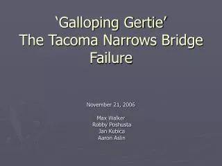
1940 Tacoma Narrows Bridge Collapse (see www.enm.bris.ac.uk/research/nonlinear/tacoma/tacoma.html). This is a linear 2nd-order ODE, which can be rearranged as. w n (= ) is the natural frequency , which equals for a RLC circuit and for a spring-mass-damper

E N D
1940 Tacoma Narrows Bridge Collapse (see www.enm.bris.ac.uk/research/nonlinear/tacoma/tacoma.html)
This is a linear 2nd-order ODE, which can be rearranged as • wn (= ) is the natural frequency, which equals • for a RLC circuit and for a spring-mass-damper • system. • z is the damping ratio, which equals • for a RLC circuit and for a spring-mass-damper • system. Second-Order System Dynamic Response • The general expression for a 2nd-order system is
The two initial conditions used are and y(0)=0. Step-Input Forcing • For step-input forcing, there are 3 specific solutions of the ODE because there are 3 different roots of the characteristic equation (see Appendix I).
Step-Input Forcing Figure 5.6
Step-Input Forcing Terminology Figure 5.7
In-Class Example • A second-order system with z = 0.5 and a natural frequency equal to 1/p Hz is subjected to a step input of magnitude A. Determine the system’s time constant.
Figures 5.9 and 5.10 Sinusoidal-Input Forcing • For sinusoidal-input forcing, the solution typically is recast into expressions for M(w) and f(w) (see Eqns. 5.62-5.64 and Appendix I).
In-Class Example • Is the RLC circuit (R = 2 W; C = 0.5 F; L = 0.5 H) underdamped, critically damped, or overdamped ? • With sine input forcing of 3sin2t: • What is its magnitude ratio ?
The Decibel • The decibel is defined in terms of a power (P) ratio, or base measurand ratio (Q), or magnitude ratio by • The one-half power point, at which the output power is • one-half of the input power, corresponds to • 10log10(1/2) dB = -3 dB
Sine Input [F(t)=KAsin(wt)]: wt 1st-Order System Summary Step Input [F(t)=KA]: t/t
Sine Input [F(t)=KAsin(wt)]: y(t) = f(KA, w/wn, z) w/wn 2nd-Order System Summary Step Input [F(t)=KA]: y(t) = f(KA, wnt, z) wnt