Nanoelectronics and Quantum Mechanics: A Good Match? - Simon Deleonibus
Explore the harmony between nanoelectronics and quantum mechanics, advancements in microelectronics cost reduction, and future prospects of CMOS devices and post-CMOS architectures.

Nanoelectronics and Quantum Mechanics: A Good Match? - Simon Deleonibus
E N D
Presentation Transcript
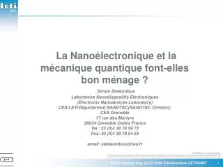
La Nanoélectronique et la mécanique quantique font-elles bon ménage ?Simon Deleonibus Laboratoire Nanodispositifs Electroniques (Electronic Nanodevices Laboratory) CEA/LETI/Département NANOTEC(NANOTEC Division) CEA Grenoble 17 rue des Martyrs 38054 Grenoble Cedex France Tel : 33 (0)4 38 78 59 73 Fax: 33 (0)4 38 78 54 59email: sdeleonibus@cea.fr E2Phi Nantes Aug 22-25 2006 S.Deleonibus LETI/D2NT
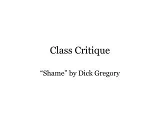
course à l’intégration / course à la miniaturisation 4G 2G 1G 512M 256M 128M Itanium 64M Pentium IV 16M Pentium III 4M 1M Pentium II Pentium 256k i486 64k i386 16k 80286 8086 4k 1k 8080 Dimension critique 4004 • loi de Moore initiale (1965) : nbr. transistors x 2 /an DRAM X4/3ans Convergence MPU X2.5/3ans Internet Portable Camera Digitale 1 milliard Home PC Introduction ULK (11niv met) Office PC microprocesseurs Introduction polymères +ALD (10niv met) mémoires dynamiques (DRAM) 10 millions Introduction Cu+H(M)SQ (9niv met) Main Frame VCR Defense Introduction Cu (7niv met) Introduction FSG(6 niv met) Introduction damascene(5niv met) Introduction vias « plugs »,CMP(4niv met) Introduction STI, salicide C.T.V. Introduction contacts « plugs »(3niv met) Introduction polycide Introduction poly gate Progrès possible grâce à l’introduction continue d’innovations E2Phi Nantes Aug 22-25 2006 S.Deleonibus LETI/D2NT
Nomadic consumer and professional products: biggest market share Three major product families few 109 tr./system • High Performance (HP) t=CV/I • Connection to power network • Low Operating Power (LOP) • Intermittent Nomadic Function • Low Stand-by Power (LSTP) Pstat= VddxIoff • Permanent Nomadic Function 109 tr./system few 108 tr./system Pdyn=CVdd2 f Ptot=Pstat+ Pdyn E2Phi Nantes Aug 22-25 2006 S.Deleonibus LETI/D2NT
La baisse des coûts, moteur de la diffusion de la microélectronique Une réduction des coûts unique dans l’histoire de l’industrie (500 000 F) Coût de 1 million de transistors (équivalent à un livre de 200 pages) (40 000 F) (3 000 F) (800 F) (200 F) (35 F) (3 F) (40 centimes) (3 centimes) 1990 1995 2000 1987 2005 1973 1977 1981 1984 E2Phi Nantes Aug 22-25 2006 S.Deleonibus LETI/D2NT
Réduction des coûts Les deux secrets de la microélectronique De plus en plus de transistors par centimètre carré de Silicium Miniaturisation 1 lot de fabrication à ST Crolles 2 : = 500 milliards de transistors !!! En 2015, l’ensemble des livres de la BNF F. Mitterrand sur une seule puce de silicium ! De plus en plus de centimètres carrés de Silicium traités simultanément Traitement collectif Plaques de silicium de 100, 200, puis 300 mm de diamètre Lot de fabrication E2Phi Nantes Aug 22-25 2006 S.Deleonibus LETI/D2NT
1999: First 20nm MOSFET Lg gate extension Gate oxide source Lm drain HDD pockets Beyond the roadmap !! Estimated metallurgical length: 4 nm(1018cm-3) SiO² hard-mask Simulation (ATHENA/SILVACOTM) 20nm poly-gate MOSFET (hybrid lithography) 1.2nm gate oxyde Gate length: 20nm Gate oxide thickness:1.2nm Extensions; BF2 pockets; n+ HDD S.Deleonibus et al. ED Letters April 2000 E2Phi Nantes Aug 22-25 2006 S.Deleonibus LETI/D2NT
Nanoscale bulk MOSFET Lg= 15nm Scattering by impurities of highly doped short channel ( room temperature) Lg gate extension Gate oxide source Lm drain HDD pockets Leakage currents and Access resistance are still issues Low field mobility degradation due to halo overlap mostly in the case of efficient SCE control LETI: G. Bertrand et al., ULIS 2003, SSE 2004 E2Phi Nantes Aug 22-25 2006 S.Deleonibus LETI/D2NT
Sommaire • Introduction et contexte • Dispositifs CMOS : physique, effets ultimes (géometries ultimes) • Feuille de route de la nanoélectronique et mise à l’échelle linéaire (ITRS and linear down scaling) • Nécessaires « Boosters » pour maintenir le progrès • Nouveaux matériaux pour amélioration CMOS: transport, parasites et courant de fuite • Nouvelles architectures CMOS Nanoélectronique • Architectures post CMOS. Opportunités mémoires • Conclusions : futurs systèmes/puce(SOC), feuille de route E2Phi Nantes Aug 22-25 2006 S.Deleonibus LETI/D2NT
Sommaire • Introduction et contexte • Dispositifs CMOS : physique, effets ultimes (géometries ultimes) • Feuille de route de la nanoélectronique et mise à l’échelle linéaire (ITRS and linear down scaling) • Nécessaires « Boosters » pour maintenir le progrès • Nouveaux matériaux pour amélioration CMOS: transport, parasites et courant de fuite • Nouvelles architectures CMOS Nanoélectronique • Architectures post CMOS. Opportunités mémoires • Conclusions : futurs systèmes/puce(SOC), feuille de route E2Phi Nantes Aug 22-25 2006 S.Deleonibus LETI/D2NT
Transistor MOS isolant de grille Lg grille Tox extension Xj source drain HDD L n(p) n(p) p(n) Canal substrat Courant d’inversion faible (« sous le seuil ») Courant de saturation (inversion forte) Tension de seuil E2Phi Nantes Aug 22-25 2006 S.Deleonibus LETI/D2NT
Saturation regime and non equilibrium Velocity saturation : vsat max≤vth where: Velocity overshoot : vinj>vsat Non equilibrium (non stationary transport). If no collision in channel : ballistic transport E2Phi Nantes Aug 22-25 2006 S.Deleonibus LETI/D2NT
Classical parasitic effects oVg oVs(0V) oVd gate current DIBL substrate current punch through SCE SCE : Short channel effect (charge sharing S-D-G) Effet de canal court(perte de contrôle charge) DIBL: Drain Induced barrier Lowering Abaissement de barrière induit par le drain E2Phi Nantes Aug 22-25 2006 S.Deleonibus LETI/D2NT
65nm 75nm Caractéristiques et effets parasites dans un transistor MOS Sous le seuil « Courant de saturation » Lg = 75 nm Lg = 65 nm Vg step = 250 mV W = 10 µm VT VT: tension de seuil DIBL(*) perçage DVT=DIBL+SCE inversion forte inversion faible(pente 1/S) SCE(*)
Parasitic effects in an ultimate MOSFET oVg oVd Direct tunneling gate current DIBL Field assisted tunneling current Punch-through SCE S-D direct tunneling Tox U0 * DIBL+SCE + punch-through : classical effects * Direct tunneling current through gate oxide * Field assisted tunneling current drain/channel diode - E I~ F2exp[-A Eg 3/2 / F] * direct tunneling currentbetween source and drain(<10nm) E2Phi Nantes Aug 22-25 2006 S.Deleonibus LETI/D2NT
Sommaire • Introduction et contexte • Dispositifs CMOS : physique, effets ultimes (géometries ultimes) • Feuille de route de la nanoélectronique et mise à l’échelle linéaire (ITRS and linear down scaling) • Nécessaires « Boosters » pour maintenir le progrès • Nouveaux matériaux pour amélioration CMOS: transport, parasites et courant de fuite • Nouvelles architectures CMOS Nanoélectronique • Architectures post CMOS. Opportunités mémoires • Conclusions : futurs systèmes/puce(SOC), feuille de route E2Phi Nantes Aug 22-25 2006 S.Deleonibus LETI/D2NT
MOSFET Engineering ITRS: 3 devices families according to applications Isat, Vdd vs Ioff ITRS 2003 1,4 3000 110 110 110 18 1,2 2500 22 1 32 2000 18 45 0,8 65 VDD(V) Isat(µA/µm) 18 1500 18 80 0,6 18 90 1000 110 18 0,4 100 110 500 110 0,2 LSTP HP LOP Low STandby Power Low Operating Power High Performance 0 0 0,001 0,01 0,1 1 10 100 1000 Ioff(nA/µm) td= CV/Isat Ptot= Pstat + Pdyn Pstat= VddxIoff and Pdyn=CVdd2 f
To double density (X2), (follow Moore’s law) then Nowadays ITRS trend from technology node to the next node !! Classical MOSFET linear scaling Channel length K Voltage U Gate oxide K Junction depth K Electric field U/K2 Channel doping U/K Parasitic capacitance K(ACox,ACj) Current (vel. sat.) U2/K(U) Delay(vel. sat.) K2/U(K) Power (vel. sat.) U3/K(U2) Speed.Power product KU2 i.e. Node n: D Node n+1: K.D Baccarani et al,IEDM 1984
Sommaire • Introduction et contexte • Dispositifs CMOS : physique, effets ultimes (géometries ultimes) • Feuille de route de la nanoélectronique et mise à l’échelle linéaire (ITRS and linear down scaling) • Nécessaires « Boosters » pour maintenir le progrès • Nouveaux matériaux pour amélioration CMOS: transport, parasites et courant de fuite • Nouvelles architectures CMOS Nanoélectronique • Architectures post CMOS. Opportunités mémoires • Conclusions : futurs systèmes/puce(SOC), feuille de route E2Phi Nantes Aug 22-25 2006 S.Deleonibus LETI/D2NT
Basic Quantum effects on energy Schroedinger’s equation: Possible solutions: • Eigenvalues for energy E and eigenfunctions (E, k - allowed values in reciprocal space) Typical significant cases in Microelectronics • Potential well : Standing waves L U0 • Energy Barrier: tunneling and combination of both: inversion layer at MOS gate oxide interface! Tb E2Phi Nantes Aug 22-25 2006 S.Deleonibus LETI/D2NT
Coexistence of 3D and 2D electron gases at a MOSFET interface2D electron gas energy splitting in triangular potential « Dead depleted » zone quantum correction quantum correction 3D gas continuum EF 2D gas discretized levels M O S Quantum confinement => degeneracy splitting (id. standing waves) • repopulation of higher energy levels with different meff • higher threshold energies required • « dead depleted » zone due to reflexion of electron wave function E2Phi Nantes Aug 22-25 2006 S.Deleonibus LETI/D2NT
Example: Global Strain on Si/SiGe D D (2) (4) hh lh D D lh hh (4) (2) D Ec =0.6x Si D Ev =0.74x Si Ge x 1 - x Si Ge Si x 1 - x Ev Ec Ev Ec Band offset and splitting Lower meff bands accessible E2Phi Nantes Aug 22-25 2006 S.Deleonibus LETI/D2NT
Strain and bandgap engineering a= 5.43 Si Si Ge Ge Si C Si x x 1 1 - - x x 1 - y y Si Si Si Si Si Si Ge x 1 - x pMOS 5.43<a<5.65 Band offset and splitting D D (2) (4) D D hh lh (2) (4) D D lh hh hh lh (4) (2) D D Ec = - 6.5y Ec =0.6x Si D Ev =0.74x Si Ge Si C x 1 - x 1 - y y Si Ge Si Si x 1 - x Ev Ec Ev Ec Ev Ec nMOS pMOS Global Compressive Compressive strain strain Tensile strain Tensile strain Tensile strain Tensile strain a= 5.43 Si Ge Si Si C C Si Si x 1 - x 1 1 - - y y y y Si Si Si Si Ge Ge x x 1 1 - - x x 5.43<a<5.65 Band Band offset offset and splitting and splitting Stressors (CESL, source & drain, salicide,…) In Si In Si Ge Ge C C No No strain strain if x=10y if x=10y 1 1 - - x x - - y y x x y y Local E2Phi Nantes Aug 22-25 2006 S.Deleonibus LETI/D2NT
Strained Si + strained Ge channels • Improved hole mobility in compressively strained Ge and electron mobility in tensely strained Si • Symetrical drain current for any dual channel CMOS E2Phi Nantes Aug 22-25 2006 S.Deleonibus LETI/D2NT LETI: Weber et al., IEDM, 2005
Short channel issues on strained architectures Global + Local Global LETI: F.Andrieu et al. VLSI Tech. Symp, June 2005,Kyoto E2Phi Nantes Aug 22-25 2006 S.Deleonibus LETI/D2NT
Ultimate transport properties in Si.Ballistic effects <v(n)> average thermal velocity Ceff gate/channel capacitance T: transmittance Lg< Lm(mean free path 100nm@300K) Ballistic and Diffusive Transport Thermionic current Tunneling current Initial injection velocity at source Reflexion on ionized dopants(channel or drain) Interface roughness Backscattering at the source , from dopants will reduce ballisticity S.Datta etal, IEDM 1998, San Francisco(CA) Dec 1998 G.Bertrand et al SNW2000 Honolulu(HI), ULIS2003Munchen(FRG) E2Phi Nantes Aug 22-25 2006 S.Deleonibus LETI/D2NT
Scaling supply voltage P = Pstat + Pdyn Pstat= VddxIoff and Pdyn=CVdd2 f Issues to address(trade of Performance & Power): room temperature operation threshold voltage control parasitic effects The most severe constraints are due to(*) : doping concentration fluctuations small volume,asymetry short channel effects lowDVT vs. VT - low Vsupply - Tox thickness,doping concentration, Xj leakage current in subthreshold regime even with S=60mV/dec(FDSOI) and VT = 0,20V (Vsupply=0,5V) we will get Ioff = 1nA/µm tunnel currents SiO2 tunneling dielectric , F-N high doping level (*) much higher impact than thermal fluctuation, energy equipartition, quantum fluctuations S.Deleonibus et al. ESSDERC 1999, Leuven, Sept 1999 E2Phi Nantes Aug 22-25 2006 S.Deleonibus LETI/D2NT
High K dielectric integration:Replacing SiO2 Si High K material Gate (poly,metal) Possible candidates SixOxN y or large mobility gap (*) SiO2 AlN Al2O3 Si3N4 Ta2O5 TiO2 BaTiO3 HfO2 ZrO2 Ec(MV/cm) 10 - 13 6 - 15 5 5 - 10 3. 5 1 3 3. 9 8. 5 10 7. 5 22 - 27 15 - 40 >1000 30 25 ε r 60 - 100 Eg(eV) 9 6. 2 7 - 8 5 4. 4 3. 2 4.3 5.68 5.16 - 7.8 (*) Bulk materials characteristics Tox=1.2nm Active area(10cm2 circuit): 1cm2 *Pstat(0.5V)= 5W => 500W/m2(1/2 AM1) *Pstat(1V) = 50W => 5kW/m2 *Pstat(1.5V) = 750W !! => 75kW/m2!! (Small Nuclear Power station to keep 50 000 PC in standby mode!! …) E2Phi Nantes Aug 22-25 2006 S.Deleonibus LETI/D2NT
Metal Workfunctions Fm « Dead depleted » zone reduce gate depletion capacitance Vacuumlevel Nb 3.99-4.30 Al 4.06-4.20 Ta 4.12-4.25 Mo 4.30-4.60 Zr 3.90-4.05 V 4.12-4.30 Ti 3.95-4.33 TaN 4.2-3.9 qSi= 4.05eV Ec mn+(Ei+0.55V) Silicon TaSixNy WSixNy WCxNy TiSixNy ZrSi2 TiSi2 TaSi2 CrSi2 MoSi2WSi2 NiSi2CoSi2 RhSi PdSi mn(Ei+0.2V) Co 4.41-5.00 Ru 4.60-4.71 W 4.10-5.20 Rh 4.75-4.98 Os 4.70-4.83 Au 4.52-4.77 Cr 4.50-4.60 Pd 4.80-5.22 Ei Midgap Eg=1.12eV WNx TiNx 4.60-4.90 qmSi(Ei)=4.61eV mp(Ei-0.2V) Re 4.72-5.00 Ir 5.00-5.70 Pt 5.32-5.50 RuO2 4.90-5.20 mp+(Ei-0.55V) Ev SMSze Physics of Semiconductor Devices 1981 J.Hauser IEDM 1999 Short Course E2Phi Nantes Aug 22-25 2006 S.Deleonibus LETI/D2NT
Sommaire • Introduction et contexte • Dispositifs CMOS : physique, effets ultimes (géometries ultimes) • Feuille de route de la nanoélectronique et mise à l’échelle linéaire (ITRS and linear down scaling) • Nécessaires « Boosters » pour maintenir le progrès • Nouveaux matériaux pour amélioration CMOS: transport, parasites et courant de fuite • Nouvelles architectures CMOS Nanoélectronique • Architectures post CMOS. Opportunités mémoires • Conclusions : futurs systèmes/puce(SOC), feuille de route E2Phi Nantes Aug 22-25 2006 S.Deleonibus LETI/D2NT
Silicon On Insulator • Smart-Cut process L Cj A A A B B Initial Initial silicon silicon Buried oxide Buried oxide tSi Oxidation Oxidation A A H H ions ions + + Smart Smart - - Cut Cut 5.10 5.10 cm cm 16 16 - - 2 2 A A implant implant improved FOM /bulk A A A Cleaning and Cleaning and bonding bonding B B B SiO2 Si M. Bruel, Elec. Lett., vol. 31, n° 14, p. 1201, 1995 -reduced parasitic capacitance -improved isolation -improved electrostatics E2Phi Nantes Aug 22-25 2006 S.Deleonibus LETI/D2NT
Co-integrated Dual Strained Channel On Insulator nFETs LTiN=14 nm 20nm sSDOI pFETs LTiN=12nm 20nm Si0.6Ge0.4 sSDOI BOX NiSi Poly Si TiN HfO2 down to 12nm gate length with a high-k/metal gate stack VT matching SOI -> LP DCOI -> HP F. Andrieu et al., IEEE SOI conf., 2005 E2Phi Nantes Aug 22-25 2006 S.Deleonibus LETI/D2NT
Fully Depleted SOI Fully depleted SOI: FDSOI VT(V) Quantum confinement N+ poly gate Bulk or PD SOI like Tsi(nm) Quantum confinement in thin film(TSi thk): Low Doped thin channel => Lower dopant fluctuations => Higher VT stability vs thickness Gate Workfunction engineering for dual gate /undoped FD channel Low VDD J.Lolivier et al, ECS Spring meeting, Paris, May 2003 E2Phi Nantes Aug 22-25 2006 S.Deleonibus LETI/D2NT
FDSOI optimization from single gate to multi gate Planar or non planar? (design/layout issue very strong) GATE GATE GATE GATE SOURCE SOURCE DRAIN DRAIN SOURCE SOURCE DRAIN DRAIN 1 1 2 2 SILICON SUBSTRATE SILICON SUBSTRATE SILICON SUBSTRATE SILICON SUBSTRATE Fringing fields through buried Fringing fields through buried With thinner buried oxide With thinner buried oxide , , fringing fields fringing fields oxide contribute oxide contribute to SCE to SCE in in substrate depletion region substrate depletion region GATE GATE GATE GATE SOURCE SOURCE DRAIN DRAIN SOURCE SOURCE DRAIN DRAIN PLANAR DGMOS 3 3 4 4 SILICON SUBSTRATE SILICON SUBSTRATE SILICON SUBSTRATE SILICON SUBSTRATE CHANNEL Adding Adding a a ground ground - - plane help plane help reducing reducing Except Except if if ground ground - - plane plane connected connected to to gate gate SCE SCE and and DIBL but DIBL but degrade Ssw degrade Ssw => Double => Double - - gate device gate device GATE BOX FINFET, Tri Gate WFET E2Phi Nantes Aug 22-25 2006 S.Deleonibus LETI/D2NT
Double gate - channel population Ravaioli, SINANO Modeling Summer School Glasgow Aug 2005 E2Phi Nantes Aug 22-25 2006 S.Deleonibus LETI/D2NT
Double gate versus Single gate(FDSOI) MOSFET by Wafer Bonding(Lg=40nm) M.Vinet et al. , SSDM 2004, Sept2004, Tokyo IST NESTOR project E2Phi Nantes Aug 22-25 2006 S.Deleonibus LETI/D2NT
Planar Double gate by wafer bonding Best Ion/Ioff trade off @ Lg=10nm published to date!! IonN(20nm) = 1250 µA/µm IoffN(20nm)= 1.3 µA/µm Lg=20nm IonN(10nm) =1130µA/µm IoffN(10nm)=7µA/µm Lg=10nm LETI: M.Vinet et al. IEEE EDL, May 2005 E2Phi Nantes Aug 22-25 2006 S.Deleonibus LETI/D2NT
WFET Non Planar Multigate Lg = 10 nm HfO2 TiN Si Excellent ION/IOFF ratio of 5.105 for a 10 nm non planar device and very good channel control LETI : Jahan et al, VLSI Tech Symposium, June 2005 Kyoto(Japan) Functional N-Fets tested down to Lg=10 nm TEM cross-section of a 60 nm silicon finger Wfet device NMOS: ION=326µA/µm, IOFF=600pA/µm @ VD=1.2V, SS=90mV/dec, DIBL=130mV E2Phi Nantes Aug 22-25 2006 S.Deleonibus LETI/D2NT
Silicon On Insulator based architecturesSubthreshold regime – optimizing electrostatics L tSi SiO2 Si SiO2 Si SiO2 Si • Subthreshold regime is limited to 60mV/decade at 300K Planar Fully Depleted SOI Planar Double-gate, FinFET Ratio : tsi/L gate x 1/4 Tri-gate,W-FET SiO2 X 1/2 Surrounding-gate (nanowire) Film thickness tSi required for a given L value x1 B.Doyle – VLSI’03 10A-2, 2003 M. Ieong et al. Science vol. 306 Dec. 2004 X 1-2 * No direct S-D tunnel introduced … E2Phi Nantes Aug 22-25 2006 S.Deleonibus LETI/D2NT
From Multichannels to Nanowires (planar and 3D) Planar multichannels: HM SiChannels Gate SiPoly /TiN/HfO2 S/D SEG Source Drain SOI BOX 200 nm • CVD growth • of single nanowire multigate devices HfO2/TiN gate stack RTB: 3D Nanowire matrix (b) CVD growth within Al2O3 pattern nanowire matrix with HfO2/TiN gate (c) MBE growth of wire heterostucture Courtesy of : T.Ernst et al., E.Hadji et al.
Sommaire • Introduction et contexte • Dispositifs CMOS : physique, effets ultimes (géometries ultimes) • Feuille de route de la nanoélectronique et mise à l’échelle linéaire (ITRS and linear down scaling) • Nécessaires « Boosters » pour maintenir le progrès • Nouveaux matériaux pour amélioration CMOS: transport, parasites et courant de fuite • Nouvelles architectures CMOS Nanoélectronique • Architectures post CMOS. Opportunités mémoires • Conclusions : futurs systèmes/puce(SOC), feuille de route E2Phi Nantes Aug 22-25 2006 S.Deleonibus LETI/D2NT
General trend towards few electron electronics E2Phi Nantes Aug 22-25 2006 S.Deleonibus LETI/D2NT
Candidates for Post CMOS Nanoelectronics E2Phi Nantes Aug 22-25 2006 S.Deleonibus LETI/D2NT
Coulomb blockade effect and Single Electron Transistor E2Phi Nantes Aug 22-25 2006 S.Deleonibus LETI/D2NT
Limits: from CMOS to SET-MOS -5 10 Lg=20nm W=10µm -6 10 Vd=100µV T=75K Vd=300µV -7 10 Vd=500µV Drain Current (A) -8 10 -9 10 T=20K -10 10 -11 10 -0,4 -0,2 0 0,2 0,4 0,6 Vg CEA /CEA-LETI: M. Specht et al. IEDM1999 G. Bertrand et al., Proceedings ULIS 2003 E2Phi Nantes Aug 22-25 2006 S.Deleonibus LETI/D2NT
Few electron phenomena will appear in future NV memory generations bit, N bit, N D D V V =3V =3V Th Th - - max max NOR Flash NOR Flash per per 10 10 3 3 Control gate NAND Flash NAND Flash electrons electrons 200 200 200 10 10 2 2 Floating gate of of Si Si Si - - - Nanocrystals Nanocrystals Nanocrystals Memories Memories Memories (NAND ) (NAND ) (NAND ) insulator Number Number 10 10 35nm 35nm 35nm 10 10 100 100 Tunn.Ox Flash Flash Technology Technology Node Node [nm] [nm] ADAMANT Control gate Control gate Nanocrystals Si substrate Defect in conventional Flash memories (Stress Induced Leakage Current): => retention Molas et al., IEDM2004, San Francisco(CA), Dec. 2004 Non Volatile (Flash) Memories N= 1012cm-2, = 5nm LPCVD Si multilevel storage!! E2Phi Nantes Aug 22-25 2006 S.Deleonibus LETI/D2NT
Molecular Memories • Memory applications of molecular electronics • Strong market demand • High density and low cost • Redundancy • Few examples • Porphyrins … • Thermal budget > 400°C • Multi-Bit/cell Bocian UC Riveside 2003 WORM Forrest Princeton 2003 Meyyappan NASA 2004 E2Phi Nantes Aug 22-25 2006 S.Deleonibus LETI/D2NT
Sommaire • Introduction et contexte • Dispositifs CMOS : physique, effets ultimes (géometries ultimes) • Feuille de route de la nanoélectronique et mise à l’échelle linéaire (ITRS and linear down scaling) • Nécessaires « Boosters » pour maintenir le progrès • Nouveaux matériaux pour amélioration CMOS: transport, parasites et courant de fuite • Nouvelles architectures CMOS Nanoélectronique • Architectures post CMOS. Opportunités mémoires • Conclusions : futurs systèmes/puce(SOC), feuille de route architectures E2Phi Nantes Aug 22-25 2006 S.Deleonibus LETI/D2NT
Integration of new functions on chip. Future System On Chip few e-memories Training, education issues to mix devices in design!! Integration of new materials for new functions with new devices exploiting new physical phenomena Pluri and inter disciplinarity!! MEL-ARI Nanoelectronics Roadmap E2Phi Nantes Aug 22-25 2006 S.Deleonibus LETI/D2NT
Perspectives: Dispositifs CMOS Nanoelectroniques • Réduction de leurs dimensions : visibilité jusqu’à Lg=5nm(2020) /encore de nombreux défis!! • Constitueront la plateforme de base de la Nanoelectronique Nouvelles fonctionnalités sur la puce=> Pluridisciplinarité • Consommation énergétique constitue le défi majeur tout en gagnant en performances (Valim: sub 1V). => Optimisation : architectures des dispositifs(*) et systèmes (*) effets quantiques rôle majeur E2Phi Nantes Aug 22-25 2006 S.Deleonibus LETI/D2NT
Construire un pôle compétitif internationalement Recherche Operationnel en 2006 4000 personnes en 2007 Merci de votre attention Industrie Education • Multidisciplinarité • Excellence • Masse critique • Plate-forme technologique 170 M€ investis par les partenaires E2Phi Nantes Aug 22-25 2006 S.Deleonibus LETI/D2NT