Download
1 / 21
240 likes | 494 Vues
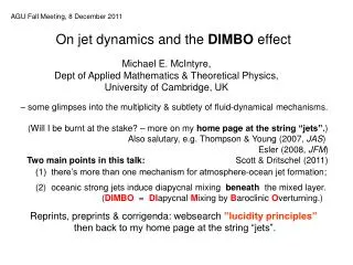
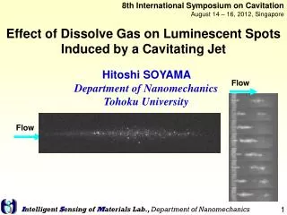
8th International Symposium on Cavitation August 14 – 16, 2012, Singapore. Effect of Dissolve Gas on Luminescent Spots Induced by a Cavitating Jet. Hitoshi SOYAMA Department of Nanomechanics Tohoku University. Flow. Flow. Impact at Cavitation Bubble Collapse. C avitation P eening CP.

E N D
8th International Symposium on Cavitation August 14 – 16, 2012, Singapore Effect of Dissolve Gas on Luminescent Spots Induced by a Cavitating Jet Hitoshi SOYAMA Department of Nanomechanics Tohoku University Flow Flow Intelligent Sensing of Materials Lab., Department of Nanomechanics
Impact at Cavitation Bubble Collapse Cavitation Peening CP Surface Modification Erosion Introduction of compressive residual stress H.Soyama et al., Surface & Coatings Technology,Vol. 205 (2011), pp. 3167-3174. Cavitation Peening Shot Peening H.Soyama and Y.Sekine, International Journal of Sustainable Engineering,Vol. 3, No. 1 (2010), pp. 25-32. Intelligent Sensing of Materials Lab., Department of Nanomechanics
Schematic of cavitation bubbles Rebound Boiling Cavitation L.A.Crum, J. Pys, C8-285 (1979). Micro jet Shock wave In water Cavitation bubble Nuclei Surface of solid 218 Plastic deformation High speed / Low pressure Liquid Decrease of speed Solid 1 Impact Cavitation peening Hot Spot Adiabatic compression Gas Pressurept atm Establishment of chemical reactor using a cavitating jet 374 100 Temperaturetw ℃ Intelligent Sensing of Materials Lab., Department of Nanomechanics
Hydrodynamic cavitation andUltrasonic cavitation (Sonochemistry) 107 Flow Chemical reactor using cavitation 106 Venturi tube 105 Flow Original technology US patent No. 6,855,208 B1 Japan patent No. 4240972 104 Cavitating jet Hydrodynamic cavitation 103 Impact energy = ×Force2×Occurrence frequency Non-dimensional cavitation impact energy Material testing 102 ASTM G134 ILS 2010-2013 ×100 Limit of aggressivity of ultrasonic 10 Material testing ASTM G32 Ultrasonic cavitation 1 Ultrasonic cleaning 0.1 102 103 0.1 1 104 10 Non-dimensional electric power to generate cavitation Intelligent Sensing of Materials Lab., Department of Nanomechanics
Cavitating Jet H.Soyama,J. Soc. Mater. Sci., Japan,47 (1998), pp. 381-387. High speed photograph of cavitating jet taken by Soyama Severe erosive vortex cavitation Ring vortex cavitation Vortex cavitation in shear layer High-speed water jet Nozzle Cloud cavitation WATER Impinging surface Schematic diagram of cavitating jet Intelligent Sensing of Materials Lab., Department of Nanomechanics
Reduction of carbon dioxide H.Soyama and T.Muraoka, Proc.20th Inter. Conf. Water Jetting, (2010), 259-267 Residual bubbles Nozzle outlet Erosion specimen Cavitation cloud p1= 200 MPa p2 = 0.2 MPa d = 0.35mm Residual cavitation bubbles Intensity V mV CO2 Room air Retention time t min Magnified view of methane CH4 peak View of the cavitation cloud and residual bubbles Intelligent Sensing of Materials Lab., Department of Nanomechanics
Reduction of carbon dioxide CO2 H2 peak H2O → H・ + OH・ H・ + OH・ → H2O 2 H・ → H2 2 OH・ → H2O2 2 OH・ → O・ + H2O 2 O・ → O2 ½ O・ +2 H・ → H2O O・ + H2O → H2O2 H2 CO2+4H2→CH4+2H2O CH4 peak CH4 Purpose Effect of Dissolve Gas on Luminescent Spots Induced by a Cavitating Jet Intelligent Sensing of Materials Lab., Department of Nanomechanics
Luminescent Spots Induced by Cavitating Jet Pressurized water Cavitation clouds observed by CCD camera with flash lamp Luminescent spots observed by EM-CCD camera Aspect of cavitating jet H. Soyama, Luminescent Spots Induced by a Cavitating Jet, Proc. ASME-JSME-KSME Joint Fluids Eng. Conf., (2011), AJK2011-33018. Intelligent Sensing of Materials Lab., Department of Nanomechanics
Experimental Apparatus and Procedures Flow Nozzle Chamber Nozzle holder Target Flow Specimen holder Figure 2: Test chamber of cavitating jet apparatus Figure 1: Test loop of cavitating jet Acoustic noise : Hydrophone (20 kHz ~ 100 kHz) High speed video camera Electron Multiplication Cooled Charged-Coupled Device camera (EM-CCD camera) Luminescence Analyzer (Photomultiplier Tube) 50 - 108 photons/cm2/s (1 count = 50 photons) Intelligent Sensing of Materials Lab., Department of Nanomechanics
Luminescent Spots Induced by Cavitating Jet Flow Figure 4: Luminescent spots of cavitating jet Intelligent Sensing of Materials Lab., Department of Nanomechanics
(a) Original images (d) Bth8 = 200 (b) Bth8 = 10 (c) Bth8 = 100 Figure 5: Luminescent spot induced by cavitating jet as a function of cavitation number and threshold level (p1 = 30 MPa, Oxygen)
103 103 102 Bth8 = 10 102 s = 0.012 101 101 0.016 Area larger than threshold level Ath mm2/s 50 Area larger than threshold level Ath mm2/s 100 0.02 100 0.008 100 10-1 10-1 150 0.005 200 10-2 10-2 Cavitation number σ Threshold level Bth8 Figure 7: Effect of cavitation number on distribution of area of luminescence spot (p1 = 30 MPa, Oxygen) Figure 6: Effect of threshold level on area of luminescence spot (p1 = 30 MPa, Oxygen) Intelligent Sensing of Materials Lab., Department of Nanomechanics 12
102 Ar 101 O2 101 Ar Air 100 Area larger than threshold level Ath mm2/s Area larger than threshold level Ath mm2/s 100 10-1 O2 N2 Air 10-1 N2 10-2 10-2 Cavitation number σ Threshold level Bth8 Figure 9: Effect of dissolved gas on area of luminescence spot (p1 = 30 MPa, Bth8 = 150) Figure 8: Effect of dissolved gas on distribution of area of luminescence spot (p1 = 30 MPa, s = 0.016) Intelligent Sensing of Materials Lab., Department of Nanomechanics 13
×105 Ar Intensity of luminescence CL count/s O2 Air N2 Cavitation number σ Figure 10: Effect of dissolved gas on intensity of luminescence (p1 = 30 MPa) Intelligent Sensing of Materials Lab., Department of Nanomechanics 14
×103 Ar Intensity of luminescence CL counts O2 Air N2 Wave length λ nm Figure 11: Effect of dissolved gas on spectrum of luminescence (p1 = 30 MPa) Intelligent Sensing of Materials Lab., Department of Nanomechanics
107 106 105 s = 0.016 Acoustic energy EA Pa2/s 104 0.01 103 0.022 0.007 102 0.013 0.019 101 Threshold level Pth Pa Figure 12 : Pulse height distribution of acoustic energy (p1 = 30 MPa, Air) Intelligent Sensing of Materials Lab., Department of Nanomechanics
107 106 pth = 1 Pa 105 3 Acoustic energy EA Pa2/s 9 104 6 12 103 102 101 Cavitation number s Figure 13 : Acoustic energy changing with cavitation number (p1 = 30 MPa, Air) Intelligent Sensing of Materials Lab., Department of Nanomechanics
Acoustic energy EA Pa2/s Approximate line Area larger than threshold level Ath mm2/s Figure 14 : Correlation between acoustic energy and area of luminescent spot (p1 = 30 MPa, Air) Intelligent Sensing of Materials Lab., Department of Nanomechanics 18
Conclusions The luminescent spots were observed in the cavitating jet by EM-CCD camera. The intensity of the luminescence spots was changing with cavitation number, and it had a maximum at certain cavitation number. The optimum cavitation number was the same as that of acoustic energy. The intensity was changing with the dissolved gas of the water. Intelligent Sensing of Materials Lab., Department of Nanomechanics
Energy of individual impactEi Ii: Acoustic energy τi: Impact duration A i : Affective area of each impact Ei = Ii τi Ai Acoustic energyIi Pi : Amplitude of pulse ρ: Density C : Acoustic speed Ii = Pi 2/ 2 ρ C Individual impact forceFi Measured by PVDF sensor Fi = Pi Ai Ei= Fi Piτi/ 2 ρ C Unknown:Pi,τi [Assumption] Pi∝Fi τi= constant ΣEi∝ΣFi 2 H.Soyama et al., J. Fluids Eng., Trans. ASME, 120 (1998), pp. 712-718. H.Soyama and H.Kumano, J. Testing and Evaluation, 30 (2002), pp. 421-431. Intelligent Sensing of Materials Lab., Department of Nanomechanics