Engineering Updates and PDR Plans Summary by Wayne Reiersen (PAC-6, December 8, 2002)
280 likes | 405 Vues
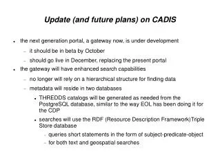
This document summarizes significant engineering developments following the Critical Design Review (CDR). Key design improvements include enhancements to modular coil (MC) structures and simplified cooling schemes. Notable changes involve the addition of a poloidal break in the MC structure to optimize plasma current ramp time and modifications to reduce keystoning impacts. The new designs aim to enhance performance, reduce costs, and improve assembly and maintenance efficiency. Overall, plans leading to the Preliminary Design Review (PDR) are being effectively implemented.

Engineering Updates and PDR Plans Summary by Wayne Reiersen (PAC-6, December 8, 2002)
E N D
Presentation Transcript
Engineering Update and PDR Plans Wayne Reiersen PAC-6 December 8, 2002 Reiersen - 1
What has happened since the CDR • Design improvements have been made • Outstanding issues are being addressed • Plans leading to the PDR have been made • Manufacturing development and R&D plans are being implemented Reiersen - 2
Design improvements and outstanding issues Added poloidal break in MC structure Adopt new MC set, make VV as large as possible for improved divertor performance and flexibility Simplified MC cooling Adopted 2x2 conductor pack in MC to minimize keystoning Simplified VV port attachment VV assembly joint tilted to avoid assembly interference, impact on vacuum seal is TBD Changed order of MC production from 6(A-B-C) to 6A-6B-6C Reduced number of PF coils from 6 to 5 Buck TF coils off CS coils rather than off separate structure Changed MC assembly from “1 at a time” to “3 at a time” Reiersen - 3
Poloidal break added to MC structure • Time constant w/o poloidal break was too long • 70ms with 3 toroidal breaks • Plasma current ramp time is 60ms • Requirements is < 20ms • Adding a single poloidal break and 15 toroidal breaks (none at field assembly joint) drops the longest time constant to 18 ms • Copper cladding on the tee will be electrically isolated and interrupted every 5-10cm Reiersen - 4
Cu cladding Cu mesh or strips 0.375 Cu clamp 0.375 DIA Stud 0.040 x 4.92 Copper Mesh 6.84 0.375 x 1.00 Screw 0.100 x 1.00 G10 Shim 4.64 Simplified MC cooling scheme adopted • High thermal conductivity clamps used • Cooling tubes are attached to clamps • Copper cladding applied to tee section over an electrical insulator – contacts clamps at attachment points • Copper mesh or strips outside ground wrap conduct heat to clamp on outside of winding pack Reiersen - 5
Adequate cooldown is achieved End of 1st heating period End of 1st cooling period (15 minute cooldown) Reiersen - 6
Adopted 2x2 conductor pack to minimize keystoning • Degree of keystoning depends on ratio of conductor thickness to bend radius • 2x2 conductor configuration should greatly reduce keystoning • Thicker (32-ga v. 36-ga) strands should reduce “splintering” • Hopefully, no compensation in the geometry of the winding surface or mechanical force to squash conductors will be required • Keystoning tests are planned for early CY03 Use 0.25x0.313-in, 32-ga conductor 4 cables per turn Reiersen - 7
1. Weld on port extension and leak check weld Port extension Port extension, part 2 Torus shell 3. Prep edges (Supplier) and weld port extension in place with full penetration weld from inside ( PPPL) 2. Cut port extension off and after final torus leak check, cut opening thru torus Port extension, part 1 Port extension, part 1 Torus shell Torus shell Simplified VV port attachment Reiersen - 8
Assembly interference resolved by tilting assembly joint 30 deg Vertical assembly flange showing interference with mod coil during assembly operation Solved by tilting assembly flanges 30 deg off vertical. Some VV supports also eliminated. Impact on seal is TBD. Reiersen - 9
Reduced number of PF coils from 6 to 5 • Adequate performance and flexibility found by combining PF3 and PF4 • New coil located in between PF 3 and PF4 • Same cross-section as PF3 • Should reduce cost (fewer coils and circuits, eliminate crown structure) and simplify assembly and maintenance (solenoid can be inserted and removed with PF3 in place) Reiersen - 10
Buck TF coils off CS coils • At CDR, it was shown that two options appeared viable • Buck TF coils off a separate structure (vertical plates and horizontal disks) • Buck TF coils off CS coils • The second option offers significant advantages and has been adopted for the PDR • Increased OD for CS coils, more V-s, less power required • Simpler CS structure should translate into lower cost Show before and after pictures Reiersen - 11
2.5-m 99-in 2.8-m 109-in 2.8-m 109-in 2.1-m 83-in 2.0-m 78-in 2.3-m 90-in Changed order of MC production and assembly • Suggestion made at CDR by D. Anderson (UW) to produce all modular coils of the same type in sequence (6A-6B-6C), rather than always changing the coil type being produced (6[A-B-C]) • Clear advantages in both MC winding form production and winding • Decision made to slide “3 modular coils at a time” instead of “1 at a time” over the vacuum vessel • Manually manipulating the SLA model at the time of the CDR showed that trying to fit a single coil over the VV and simlutaneously mate the “wings” of the MC into the “slots” in the adjacent MC was more difficult than pre-assembling the 3 MC’s in a half field period and sliding them over the VV • Expanding the VV to provide more room for the divertor exacerbates this difficulty • No schedule impact on first plasma, takes VV off critical path Reiersen - 12
Incorporating the new MC design and expanding the VV is the major outstanding issue • Physics has been working hard to provide a healed MC set with increased coil-to-plasma spacing for improved divertor performance • Key engineering metrics have been incorporated into the optimization (max coil current, min bend radius, min coil-to-coil spacing) and have been preserved or improved in candidate MC sets • Engineering has developed tools to optimize the MC trajectory during field period assembly to facilitate expanding the VV and make more room for a divertor • Updating the conceptual design with a new MC set and VV is the pacing item for the PDR Reiersen - 13
VV size is limited by modular coil assembly constraint Reiersen - 14
Algorithm developed to optimize trajectory with 6 DOF • Sample run with M47 coils and expanded VV boundary • Plasma fits nicely inside FW but min separation is too small • Run to be repeated with new coils and plasma boundary Reiersen - 15
Plans leading to the PDR have been made • Expectations for the PDR have been defined • Work plans leading to the PDR have been coordinated, incorporated in the project control system, and are being tracked • Plans for manufacturing development and prototype fabrication for the vacuum vessel and modular coils are being implemented Reiersen - 16
Expectations for the PDR • A June PDR is planned for the VV and Modular Coils • The conceptual design and cost and schedule estimates for all other WBS elements will be updated at that time • PDR Requirements • Performance requirements have been defined • A design has been developed that fully meets those requirements • All feasibility issues have been resolved • Interfaces with other systems have been fully defined • Plans for assembly, installation, and test are established • Models and drawings have been developed, reviewed, and released at the Preliminary Design level • A sound and stable basis exists for proceeding with Final Design Reiersen - 17
Key activities leading to the PDR This will be replaced… Reiersen - 18
Implementation of manufacturing development and R&D plans • 4 vendors (2 for the MC and 2 for the VV) will be brought on board in January ’03 to do mfg development and prototype fabrication • The vendors for the production units will be selected from among those participating in this next phase • Modular coil winding R&D is being done in-house at PPPL Reiersen - 19
VV manufacturing development and prototype fabrication • Manufacturing development activities will be conducted by 2 subcontractors to support the VV PDR. • Manufacturing methods for fabricating the VV will be identified. • Recommendations for improving the VV design and performing additional mfg development activities will be solicited. • Preliminary MIT/QA Plans will be developed and used as the basis for budgetary cost and schedule estimates. • The subcontractors will fabricate a full scale 20º prototype VV segment. • The subcontractors will submit a final MIT/QA plan and a fixed price cost and schedule proposal for the production units Reiersen - 20
20º prototype vacuum vessel segment Reiersen - 21
MC winding form manufacturing development and prototype fabrication • Deliverables are the same as for the vacuum vessel • Manufacturing development activities will be conducted by 2 subcontractors to support the Modular Coil PDR • The subcontractors will fabricate a full scale prototype (Type A) modular coil winding form (later used for winding R&D) • The subcontractors will submit a final MIT/QA plan and a fixed price cost and schedule proposal for the production units Reiersen - 22
In-house winding R&D • Winding R&D at PPPL has been initiated in FY03 • Key elements • Perform keystoning tests • Determine winding material properties and allowables • Develop VPI process • Develop molding process • VPI molded test samples in small oven (pre-PDR) and autoclave (post-PDR) • Wind, mold, and VPI full scale prototype coil (post-PDR) Reiersen - 23
Keystoning tests • Winding form being designed • Nine insulated turns using four (4) conductors per turn will be wound onto form • “Faro” mechanical measuring arm will be used to measure tolerance build as a result of conductor keystoning Reiersen - 24
Material tests to determine properties and allowables • SOW being drafted identifying all necessary tests • Mold designed and fabricated for 1st tensile specimens • VPI of 1st tensile specimens expected this week Reiersen - 25
Develop VPI process • CTD 101K selected as the resin system for impregnating modular coils • Epoxy characterization underway (cure cycle, viscosity, etc.) • Will be used to VPI 1st tensile specimens and UT coil • Existing small vacuum oven and viscometers will be used • R&D is being conducted in TFTR Basement Reiersen - 26
Develop molding process • Wet wrap of winding pack is planned to form pressure boundary for VPI • Molding process will first be tested on straight samples, VPI in small oven • Molding process tested on actual coil sections next • Larger sections and a full scale prototype will be molded after the PDR, VPI in autoclave Reiersen - 27
Summary • We have a better design • Substantial configuration improvements have been made since the CDR, no new “showstoppers” have been identified • We have a plan • Work plans have been put in place for a June PDR and cost & schedule review • We are moving forward • Critical path manufacturing development and winding R&D activities are moving along well • Incorporating the new MC design and expanded VV are the pacing items Reiersen - 28