Download
1 / 22
220 likes | 239 Vues
LBT Diagnostics Installation Update. Dan Padrazo Diagnostics & Instrumentation Group Feb 1, 2012. Acknowledgements. Om Singh Timur Shaftan Igor Pinayev Kurt Vetter Bernie Kosciuk Yong Hu Ray Fliller Sergei Seletskiy Dick Hseuh Tony Caracappa Mike Johanson. Overview.

E N D
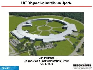
LBT Diagnostics Installation Update Dan Padrazo Diagnostics & Instrumentation Group Feb 1, 2012
Acknowledgements Om Singh Timur Shaftan Igor Pinayev Kurt Vetter Bernie Kosciuk Yong Hu Ray Fliller Sergei Seletskiy Dick Hseuh Tony Caracappa Mike Johanson
Overview • Diagnostics Technical Support for Installation • Diagnostics for Linac To Booster Transport Line • Integration Model of LBT. • Illustration of LBT Diagnostics Part 1 & 2. • Illustration of LINAC BPM / PUE. • Installation of LBT Diagnostics Part 1 • Integration of LBT Diagnostics Part 1 • Electronics, Racks, Controls Interface • Injector Diagnostics Installation Schedule • Summary / Status
Diagnostics Technical Support for LBT Installation Group Leader – Om Singh Project Engineer – Dan Padrazo Project Engineer- Bernie Kosciuk Engineer – Bel Bacha Engineer – Tony Caracappa AP – Igor Pinayev AP - Sergei Seletskiy Technical Supervisor- Wayne Rambo Technical Support – Jack Tallent, Chris Danneil, Marshall Maggipinto, Artie Munoz, Al Borelli, Dennis Poshka,George Stenby(MOU), Dave Tupper(JS), Bill Brannigan(JS)
Integration Model LBT Part 1 & 2 LBTL-Part 2 LBTL-Part 1
Illustration LBT Diagnostics-Part 1 2 Part1 Diagnostics
Illustration LBT Diagnostics-Part 2 2 Part2 Diagnostics
BPM Supported in LINAC LIN-P5 LIN-P3 LIN-P1 LIN-P4 LIN-P2 LINAC BPM
Pre-Installation Work (LBT-BPM Chamber/PUE) TL Button/Feed-thru assembly 11-15-11 SA BPM Assembly 11-12-11 LA BPM Chamber- populated w/Button Feed-thru Assembly (11-12-11) 40mm x 90mm Elliptical Fixture using single wire test LA BPM Assembly 11-12-11
Pre-Installation Work (Testing Energy Slit/ Flags) Test Rack used for Diagnostics Electronics and Controls. Test Stand using SP-1005 Girder top for SA Flag testing (11-23-11) Energy Slit & LA Flag mounted on Production Version SP-1006 Girder, captured in portable clean room (11-4-11)
Pre-Installation Work (FCT/ICT) In-Flange Bergoz FCT- Cleaned and prepared for install. FCT-CF6”3/4-96.0-UHV-20:1-H FCT-Test Fixture for Pre test prior to install Beam Charge Monitor Chassis BCM-IHR Module In-Flange Bergoz ICT – Cleaned and prepared for install. ICT-CF6”-60.4-UHV-070-20:1-H
Tunnel Installation Work (LBT Part 1 & 2) LBT Component Install Part 1(1-4-12) LBT Girder Install Part 1(11-7-11) LBT Part 2 (11-30-11) LBT Part 2 Diagnostics Cables Pulled (12-6-11)
Cable Description / Specification • LMR-240FR – Low Loss Coax Cable (RF BPM / ICT) • Attenuation (db/ft) .057db @500Mhz • Jacket Diameter .240” • Custom trim to relative timing specification of +/-25pS, with a delta phase specification of 4.5 degrees @ 500Mhz. • LMR-400FR – Low Loss Coax Cable (RF BPM / FC) • Attenuation (db/ft) .028db @500Mhz • Jacket Diameter .400” • LMR-900FR – Low Loss Coax Cable (FCT) • Attenuation (db/ft) .014db @500Mhz • Jacket Diameter .900” • SIO2 – Silicon Dioxide Low Loss Coax Cable (RF BPM) • Attenuation (db/ft) .06db @500Mhz • Jacket Diameter .141” • Semi-Rigged, fired glass hermetically sealed assembly • Commercially fabricated as a straight length and a relative timing specification of +/- 25ps, with a delta phase specification of 4.5 degrees @ 500Mhz
BPM Cable Work LMR-240FR Cable install (11-8-11) Pneumatic Crimp tool Mobile Cart for Cable Time / Terminate (1-10-12) SIO2 Cable Assembly (1Meter)
BPM / PUE / PTC Module Installation Patch Panel Interface to PTC for LINAC LINAC PTC Module Install (11-8-11) LIN-P5 BPM PUE Assembly w/LMR-240FR Cables (1-15-12) LBT-P1 BPM SA Chamber Assembly at SP-1002 Girder w/SIO2 Cables Installed 1-20-12
LBT Flags Installation SA Flag Assembly at SP-1005 Girder LA Flag Assembly at SP-1006 Girder Tunnel patch for Energy Slit / Flag at SP-1006 Tunnel patch panels for flag Pneumatics / PLC / Controls
LBT Beam Dump / Faraday Cup Install Dump 1 at SP-3000 Girder (1-20-12) Dump 2 at SP-4000 Girder (1-20-12)
LBT Electronics Rack Layout cPCI Acqiris digitizer cPCI CPU board
Diagnostics Electronics / Cable Management (RG-Q) BPM receiver LINAC (Front View) PLC Controls for Flags (Rear View) Cable Route into Rack Penetrations (Top View) Custom patch Panel /SR for LMR Cables (Top View)
Summary / Status • Implemented Resources loaded Work Plan • Diagnostics Component Tunnel Installation - Complete • Diagnostics Cable pull, Time, Termination - Complete • Diagnostics Electronics Install in Rack RG-Q1,2,3,4 - Complete • Post installation Diagnostics Sub-System Functional testing - Complete • System testing in progress, expected to be complete 2-13-2012