Download
1 / 13
140 likes | 193 Vues
Learn to determine stress and deformation of a seatbelt component using Patran 2005. Create geometries, partition surfaces for meshing, apply loads, and troubleshoot for accurate results.

E N D
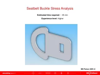
Seatbelt Buckle Stress Analysis Estimated time required: ~ 35 min Experience level: Higher MD Patran 2005 r2
What You Will Learn… • Creating simple geometries with Patran and trimming excess geometries. • Partitioning geometry into different surfaces to use ISO meshing (Quad4 elements). • Using one-way mesh seed bias to increase the density of the mesh at the location of interest.
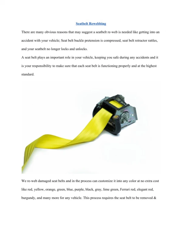
Problem Description Determine the stress and deformation of the prototype seatbelt component shown in the figure below. • For simplicity we will analyze only the right, tongue, portion of the part. • A force of 1,000 lbf is to be applied at the right of the negative hole of the tongue portion. (it is important to apply the force to the rounds too) • Left edge of tongue is constrained in all directions. • Component is made with quenched and tempered steel (ASTM-A514 grade P) and is 1/8” thick. (If you cannot find the material properties for this steel, click on this link and you will be guided to the page)
Problem Description – Details of the Tongue of Seatbelt Note: All units illustrated are in inches
Creating Geometry • Select Create / Curve / XYZ from the drop down menus. • In Vector Coordinate List enter <2 0 0>. • In Origin Coordinate List enter <0 0 0>. • Click Apply button. a b c d • Select Create / Curve / 2D ArcAngles from the drop down menus. • In the Radius text box enter 0.5. • For the Start Angle enter 270. • For the End Angle enter 0. • For Center Point List enter [2 0.5 0] • Click Apply button. a b c d e Using this techniques, complete the remaining geometries for the seatbelt tongue. f
Creating Surfaces • Select Create / Surface / Curve from the drop down menus. • From the Option drop down menu select 2 Curve. • In the Starting Curve List text box select the outer curve (in this case curve 5). • In the Ending Curve List text box select the outer curve (in this case curve 13). • Click Apply button. a b c d e To create the remaining surfaces, you will need to break up single curves into two different curves. • Select Edit / Curve / Break from the drop down menus. • From the Option drop down menu select Point. • In the Curve List text box select the curve that you want to be broken up into two curves (this case curve 30). • In the Break Point List textbox enter the exact point where the break should occur (this case [1.375 2.5 0]. If the Point is on a arc and the exact point is not known, estimate somewhere in the middle and click on the location. The coordinate will be automatically calculated. a b c d e
Creating Surfaces The seatbelt tongue will consist of 10 surfaces as illustrated to the right. Using the same techniques from the previous slide, complete the remaining surfaces.
Creating Mesh Seed – One Way Biased • Select Create / Mesh Seed / One Way Bias from the drop down menus. • Click on the Num Elems and L2/L1 radio button. • In the Number text field enter 40. • In the L2/L1 text field enter 2.5. • In the Curve List text field select the curve which one way biased mesh seed is to be applied. (in this case it was surface 1.3) • Click Apply button. a b c d e f Apply one way biased mesh seed on corners so that the mesh density can increase in the area of interest (stress concentration area).
Trouble Shooting • If the analysis does not run: • make sure you remembered to equivalence the model to remove the extra nodes • make sure the it is a closed geometry. • make sure the surfaces are properly created. • If the results do not match the given results: • Check the material are created and applied properly. • The load and boundary conditions are correct. • Mesh is dense enough to provide accurate answers
Further Analysis • The same seatbelt tongue has been modeled using a CAD software and exported into Parasolid format. Using this provided 3D model, apply the same loads and boundary conditions and compare your results to the ones already obtained. (Use any mesher as you would like). • What are the differences in stress and deformation if the total load is not applied to the rounds and only in the vertical element? • What modification can be made to obtain a higher factor of safety? Change your model accordingly.