Download
1 / 51
530 likes | 1.04k Vues
Texture Mapping Ltjg Omer Arisut Turkish Navy. Texture Mapping. -A texture is a rectangular pixel map that is mapped onto some surface -Texture mapping is the process of mapping a scanned or hand-drawn image (called the texture map or simply the texture) onto a polygon.

E N D
Texture Mapping • Ltjg Omer Arisut • Turkish Navy
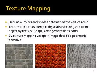
Texture Mapping -A texture is a rectangular pixel map that is mapped onto some surface -Texture mapping is the process of mapping a scanned or hand-drawn image (called the texture map or simply the texture) onto a polygon.
Texture Mapping Methods -2D texture mapping Color, bump, displacement, transparency mapping, etc. 3D texture mapping Reflection and solid texture mapping
2D texture mapping -A ‘cheap’ way of enhancing the the surface definition In real life, many surfaces are multi-colored 2D texture mapping involves applying a 2D image to the surface of a 3D object Textures may be ‘real’, manually generated or procedurally generated The process of applying the texture is the ‘mapping’ The two mapping processes: Projecting the image onto the surface Stretching the image to fit on the surface
Basic Idea • Take a source polygon defined within a texture map and project it onto a destination polygon • The texture map is most often defined in rectangular (u,v) coordinates called texels.
Operations in Texture Mapping • - Determining which texture pixel (texel) should be used for the mapping on to the target fragment (done during scan conversion) • - Filtering the texel color value (with or without mipmapping)—Pixel Operation • - Blending the texel with the fragment -- Pixel Operation
Projection mapping -In projection mapping the image is projected through space Wherever it ‘hits’ the surface the surface becomes the color of the texture Cylindrical projection, Rectangular Cylindrical projection, Spherical projection, and Planar projection are projection mapping methods.
CylindricalMapping • Applying a texture map to a cylinder is easy if we use cylindrical coordinates. The texture just wraps around the cylinder.Image is bent into a cylinder before projection takes place. Object is then placed ‘in’ the cylinder
Spherical Mapping We can apply a texture map to a sphere by using spherical coordinates. Image bent onto an imaginary sphere before projection. Object placed ‘in’ sphere
Planar Mapping a planar projection on a cube will have one side mapped with the texture while the other sides show the texture streaked
Parameterised mapping • Imagine printing the texture image onto thin transparent film • Then stretch the film over the surface • This is the principle of parameterised texture mapping • The 2D texture image is an array of rectangular pixels • These can be referenced by Cartesian coordinates, usually with the lower left pixel being (0,0) (and for a 512 x 512 image the top right being (511,511)) • Each pixel rectangle is then mapped to a corresponding area of the 3D surface • You therefore have to divide the surface into the same number of steps • The surface patch is defined to use the coordinate system U and V to specify locations on it • The area defined by (0,0) on the surface has the color applied to it from the image pixel at (0,0)
Parametrization • Each (x,y) vertex in the destination polygon is the projected (u,v) vertex from the source polygon. The projected (x,y) pixels drawn in the destination polygon are taken from the corresponding original (u,v) pixels in the source polygon.
Parametrization • Define a mapping from object space (x,y,z) to texture space (s,t).
Parameterised mapping • Example scene without textures Same scene with textures applied
Texture Mapping in Terms of the Shading Equation Texture mapping can be used to alter some or all of the constants in the shading equation. We can simply use the texture as the final color for the pixel, we can just use it as diffuse color, or we can use the texture to alter the normal.
Texture Mapping in Terms of the Shading Equation The result Sphere Texture Map I = Texture(s,t) Cd = Texture(s,t)
Bump Mapping -Texture map can be used to alter the surface normal of an object. -The actual shape of the surface is unchanged. -It is only being shaded as if it were a different shape! -This technique is called bump mapping. -The texture map is treated as a single-valued function which represents height.
Bump Mapping • Bump mapping can give the visual illusion of the presence in the surface of small bumps, holes, irregularities, carvings, engraving, scales, and so on; if managed efficiently, this can be achieved at a very small fraction of the rendering time that would be necessary for an object with similar characteristics modeled as geometry.
Bump Mapping Sphere w/ Texture Map Bump Map Sphere w/ Texture & Bump Maps
Bump Mapping Cylinder w/ Texture Map Bump Map Cylinder w/ Texture & Bump Maps
Bump Mapping Bump maps are good for subtle details like panel lines and rivets
Displacement Mapping The texture map is used to actually move the surface point. This is called displacement mapping. This is fundamentally different than bump mapping. This technique is like a texture map each pixel holding a displacement value.
Displacement shaders applied to a box and a sphere in a simple scene. Accurate computation of shadows and refractions is illustrated
Diffusion Mapping Depending on values, the surface will appear dull and dirty or bright and clean. Works well for illustrating grease grime and worn paint
Color Mapping These are full color images that are applied to the model's surface. Any markings or graphics are incorporated into the color map. The completed model below wears a total of 131 texture maps.
Transparency Mapping • Texture mapping may be used to lay transparent or semi-transparent objects over a scene by representing transparency values in the texture image as well as color values. This technique • is useful for simulating clouds • [Gardner 85] and trees for • example, by drawing • appropriately textured polygons • over a background.
Light Mapping Light maps are stored pre-computed lighting information that is mapped on to surfaces. Quake uses light maps in addition to texture maps.Both texture maps and light maps are multiplied together at run-time, and cached for efficiency.
Light Mapping More Examples
Noise and turbulence • We sometimes want to add random variations to our texture, but in a controlled way. Noise and turbulence are very useful tools for doing just that. • To calculate the noise value of any point in space, we first determine which cube of the lattice the point is in. Next, we interpolate the values of the 8 corners of the cube:
Noise and turbulence • Original Object Trilinear Noise Triquadratic Noise
Noise and turbulence • Turbulence • Noise is OK, but it’s not enough all by itself. It can be made more interesting by turbulence. A simple turbulence function can be computed by summing many different frequencies of noise functions
Noise and turbulence • Marble Example • Turbulence can be used to generate • beautiful 3D marble textures, such as • this marble vase created by Ken Perlin. • The idea is simple. Fill space with black • and white stripes, using a sine wave function. • Then use turbulence at each point to distort • those planes.
Perspective Correction • Textures look fine, mapped to a polygon when viewed face-on. • But if viewed at an angle, we can get perspective distortion. • The problem is that texture coordinates do not vary linearly in screen space. • If we interpolate texture coordinates linearly in screen space, we get the image on left left below, when what we would like is the image on the right.
Perspective Correction • Perspective Distortion Perspective Correction
Sampling • Textures look pretty good when the size of the texture map is about the same size as the polygon on the screen • Polygon Texture Map Polygon w/ Texture Map
Sampling • But if we zoom in too close, many pixels on the screen map to the same texel. If we select the closest texel, we get the image on the left below. We can do better by bilinearly interpolating the 4 texels surrounding the sample, which gives us the image on the right below.
Mip Mapping • Zooming out brings a problem such as trying to display high frequencies in the texture with too small of a sampling rate. • The solution is to pre-filter the texture. • A mip-map is a series of down-sampled versions of a texture, each at half the resolution of the previous. Each texture lookup is performed at the appropriate mip-map level, based on the size of the pixel projected into texture space.
Mip Mapping • Point Sampling Mip-Mapping
Cellular Textures Image from A Cellular Texture Basis Function, by Steven Worley, SIGGRAPH'96 Image from Cellular Texture Generation, by Kurt Fleischer, David Laidlaw, Bena Currin, and Alan Barr, SIGGRAPH '95
Environment Mapping • Environment mapping is a technique that simulates the results of ray-tracing. Because environment mapping is performed using texture mapping hardware, it can obtain global reflection and lighting results in real-time. • Environment mapping is essentially the process of pre-computing a texture map and then sampling texels from this texture during the rendering of a model. The texture map is a projection of 3D space to 2D space.
Environment mapping • Environment mapping [Greene 86] may be achieved through texture mapping in one of two ways. • First way is through texture mapping requiring six texture images, each corresponding to a face of a cube, that represent the surrounding environment.
Environment mapping • At each vertex, a reflection vector is computed. • This reflection vector indexes one of the six texture images. • The image is mapped onto the polygon using projective texturing. • If a polygon has reflections into more than one face of the cube, then the polygon is subdivided into pieces, each of which generates reflections into only one face
Environment mapping • The second method is to generate a single texture image of a perfectly reflecting sphere in the environment. This image consists of a circle representing the hemisphere of the environment behind the viewer.
Solid Mapping • Mapping a solid texture onto a solid object is a fairly straighforward idea but proved to be challenging to implement. We represent volume data by creating z files, representing parallel slices, of size x by y, where x, y, and z are the dimensions of the volume. The data we used was in ppm format for easy reading.
Questions • 1- What are the ways to generate a texture? • Textures may be ‘real’, manually generated or procedurally • generated. • 2- What is the use of light maps? • Light maps are stored pre-computed lighting information that is • mapped on to surfaces • 3- Does the actual shape of the object change in “Bump Mapping”? • No, the actual shape of the surface is unchanged. • It is only being shaded as if it were a different shape!