Download
1 / 54
540 likes | 693 Vues
FOWLER CHAPTER 8 LECTURE 8 ALTERNATING CURRENT AND VOLTAGE. CHAPTER 8 AC AND VOLTAGE P.201. FOR A DC WAVEFORM IN A SIMPLE CIRCUIT THE OUPUT IS ALWAYS CONSTANT, EXCEPT WHEN THE CIRCUIT IS SWITCHED ON/OFF. DC WAVEFORMS CAN BE + OR - BUT NEVER BOTH. V. +. -. t. TYPES OF AC WAVEFORMS.

E N D
CHAPTER 8 AC AND VOLTAGE P.201 FOR A DC WAVEFORM IN A SIMPLE CIRCUIT THE OUPUT IS ALWAYS CONSTANT, EXCEPT WHEN THE CIRCUIT IS SWITCHED ON/OFF. DC WAVEFORMS CAN BE + OR - BUT NEVER BOTH. V + - t
TYPES OF AC WAVEFORMS SINUSOIDAL MOST COMMONLY USED IN DIGITAL ELECTRONICS SAWTOOTH( TV,RADAR)
CYCLE P.203: ONE WAVEFORM THAT DOES NOT REPEAT ITSELF ½ CYCLE .25 S PERIOD (T) : TIME TO COMPLETE ONE CYCLE.( IN THIS CASE .25 SECONDS)
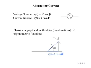
FREQUENCY( f ) : # OF CYCLES/SECOND Time (sec) FORTHIS WAVEFORM f = 1 CYCLES/SEC HERTZ: UNIT OF FREQUENCY . FOR THE ABOVE WAVEFORM f = 1 Hz f =1/T OR f =1/λ AMPLITUDE: (a) HEIGTH OF THE WAVEFORM.
EXAMPLE: FIND THE FREQUENCY FOR THE WAVE FORM BELOW. =1/T = 1/20ms = 1/.002 = 500Hz
PEAK VP: MAX. VALUE OF WAVEFORM. CAN BE EITHER + OR- SINCE WAVEFORMS ARE NOT CONTINIOUS AT ALL TIMES THE AVERAGE VALUE IS USED. VAV =AVERAGE VALVE VAV =0.637VP VP = 1.57VAV } USEFUL IN AC/DC CIRCUITS M/U#38 3:30-12:40 http://www.youtube.com/watch?v=7QCxbwzikFk
RMS( ROOT-MEAN-SQUARE) WHAT IS THAT? 1. WAVE FORM IS DIVIDED UP INTO SMALL INTERVALS. 2. EACH INTERVAL IS SQUARDED. 3. MEAN (AVERAGE) OF SQUARED VALUE IS FOUND. 4. SQUARE ROOT OF THE MEAN IS CALCULATED. \
RMS value is an equivalent DC value which tells you how many volts or amps of DC that a time-varying sinusoidal waveform is equal to in terms of its ability to produce the same power. For example, If you have mains supply of 240Vac and is assumed an effective value of “240 Volts RMS”. This means then that the sinusoidal RMS voltage from the wall sockets of a home is capable of producing the same average positive power as 240 volts of steady DC voltage as shown below.
SINE WAVES REVIEW: WHEN A CONDUCTOR MOVES THRU A MAGNETIC FLUX, A VOLAGE AND CURRENT ARE INDUCTED IN THE CONDUCTOR. THE AMOUNT OF INDUCED VOLTAGE IS A FUNCTION OF THE AMOUNT OF FLUX CUT BY THE CONDUCTOR Magnetic Induction in a Wire http://www.youtube.com/watch?v=P3kJd3MDeuk&list=UUOc3q8ChcDYyeyFROxLDhuw
AMOUNT OF FLUX CUT DEPENDS ON • SPEED OF THE CONDUCTOR • FLUX DENSITY • ANGLE THAT CONDUCTOR CROSSES THE MAGNETIC FILED. • SEE FIG. 8.8,P208 • DIRECTION OF INDUCTED CURRENT DEPENDS ON • DIRECTION CONDUCTOR IS MOVING. • POLARITY OF THE MAGNETIC FIELD.
LEFT HAND RULE. P.209 http://www.youtube.com/watch?v=KUrMt6ic53o&list=UUOc3q8ChcDYyeyFROxLDhuw Building a Generator: size of induced current
PRODUCING SINE WAVES. P.209 YOU CAN GENERATING A SINE WAVE BY ROTATING A CONDUCTOR THRU A MAGNETIC FIELD. Commutators: Basics on AC and DC Generation http://www.youtube.com/watch?v=ATFqX2Cl3-w&list=UUOc3q8ChcDYyeyFROxLDhuw&index=6
http://www.youtube.com/watch?v=P83Qa3Chb7I&list=UUOc3q8ChcDYyeyFROxLDhuwhttp://www.youtube.com/watch?v=P83Qa3Chb7I&list=UUOc3q8ChcDYyeyFROxLDhuw Slip Rings and Brushes - Generators ONE ROTATION OF A CONDUCTOR THRU 4 POLES GENERATES TWO CYCLES OF VOLTAGE/CURRENT. YOU TUBE:AC Motor Animation Video http://www.youtube.com/watch?v=Q4FlUP-kJe8
TO MAKE A AC GENERATOR YOU NEED THE FOLLOWING PARTS: WINDINGS,MULTILOOPED COIL. ARMATURE: WINDING WOUND ON A SILICON STEEL CORE. SLIP RINGS (COMMUTATORS) BRUSHES FIELD COILS YOU TUBE,How generator works by Khurram Tanvir http://www.youtube.com/watch?v=i-j-1j2gD28
OUTPUT OF A GENERATOR DEPENDS ON 1. # OF TURNS IN THE ROTATING COILS. 2. SPEED THAT THE COILS ROTATE. 3. FLUX DENSITY OF THE MAGNETIC FIELD. YOU TUBE:AC Generator Action.avi http://www.youtube.com/watch?v=mCvXa_VVFh4
GENERATOR FREQUENCY P.212 • FREQ. OUTPUT OF A GENERATOR DEPENDS ON • # OF PAIRS OF MAGNETIC POLES. • ROTATIONAL SPEED OF THE COILS. FREQ. GEN.OUT =(R PER MINUTE)X(PAIRS OF POLES)/60 EXAMPLE:WHAT IS FREQ. OF 6 POLE GENERATOR ROTATING AT 1200 RPM? AC GENERATOR BUILT IN 1890 http://www.youtube.com/watch?v=d_aTC0iKO68 YOU TUBE,Magnetism: Motors and Generators START AT 25SEC The Frequency of an AC Generator www.wisc-online.com/ViewObject.aspx?ID=IAU14108
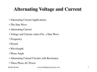
Advantages of A.C. over D.C. / Why generation is done in A.C. • AC CAN BE GENERATED AT HIGH VOLTAGES. • HV AC GENERATORS ARE SIMPLER AND CHEAPER THEN DC GENERATORS. • AC CAN BE STEPPED UP OR DOWN WITH TRANSFORMERS. The Mechanical Universe - 38 - Alternating Current,17:00-21:00 AC vs.DC http://www.youtube.com/watch?v=7QCxbwzikFk
3 PHASE AC P.213 POWER PLANTS PRODUCE 3 PHASE AC. EACH PHASE IS SEPARATED BY 120°. P. 214
http://www.youtube.com/watch?v=fGPdPKMSpv8 3 Phase AC Motor Working Principle
(b) Output waveform (red) for three cycles of a 200 Vp-p input to a single-phase half-wave rectifier (a) Output waveform (red) for three cycles of a 200 Vp-p input to a three-phase half-wave rectifier Fig. 8-24 P.220 A comparison of half-wave rectification of single-phase and three-phase ac.
(a) Output waveform of a full-wave single-phase rectifier with an input of 200 Vp-p. (a) Output waveform of a full-wave three-phase rectifier with an input of 200 Vp-p. Fig. 8-25 P.221 Comparison of full-wave rectification of three-phase and single-phase ac.
3 PHASES ARE CONNECTED SO THE LOAD CAN BE CARRIED ON 3 CONDUCTORS FROM THE POWER PLANT TO THE USER. 3 PHASES ARE CONNECTED IN EITHER DELTA OR WYE CONFIGURATION.
120/208 3-Phase Wye: 208 volts are present between all 3 phases. 120 volts between all 3 phases to Neutral
3 PHASE 120/208V, 4 WIRE WYE SYSTEM LINE 1 120 V PHASE 1 120 V 208 V NEUTRAL TO 3 PHASE LOADS PHASE 3 120 V 208 V 120 V PHASE 2 120 V LINE 2 GROUND 120 V 208 V LINE 3 UNDER LOAD:LINE AND PHASE CURRENTS ARE NOT EQUAL. SINCE 2 PHASE VOLTAGES ARE SEPARATED BY 120º , THEY CANNOT BE ADDED TOGETHER ILINE = 1.732IPHASE VLINE = 1.732VPHASE VLINE2 = 1.732(120V) = 208V SINGLE PHASE 120 V ARE CONNECTED BETWEEN THE NEUTRAL AND ANY ONE LINE. SINGLE PHASE 208 V CIRCUITS ARE CONNECTED BETWEEN ANY 2 OF THE 3 LINES. 3 PHASE 208 V ARE CONNECTED ACROSS 3LINES.
ADVANTAGES OF 3 PHASE (Φ) SYSTEMS. 1.MORE EFFICENT USE OF COPPER. 2 PROVIDES A MORE CONSTANT LOAD ON THE GENERATOR. 3. MOTORS ARE LESS COMPLEX 4. 2 OUT OF 3 PHASES ARE PROVIDING CURRENT AT ANY TIME.
ONE OF THE MANY PRESENT DAY PLUG AND SOCKET FOR ELECTRIC CARS
Leviton Evr-Green Base Level 1 GFCI Guide Light Receptacle for Electric Vehicles
The lithium-ion batteries can store up to 24kWh of electricity, which is sufficient to supply an average Japanese household for about two days. This system underscores an additional attribute of EVs: vehicles which can be used as a storage battery whether they are moving or stationary.
Nissan Motor Co., Ltd. will launch the "LEAF to Home" power supply system, which can supply electricity from batteries onboard in Nissan LEAF electric vehicles (EV) to homes when used with the "EV Power Station" unit developed by Nichicon Corporation. "LEAF to Home" is an industry first backup power supply system that can transmit the electricity stored in the large-capacity batteries of Nissan LEAFs to a residential home.