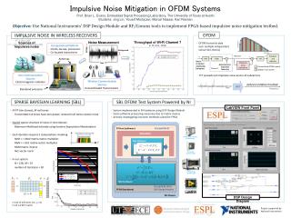
Download
1 / 14
240 likes | 1.08k Vues
Noise in Communication Systems. Professor Z Ghassemlooy Electronics and IT Division School of Engineering Sheffield Hallam University U.K. Contents. Interference Types of noise Electrical noise Gaussian noise White noise Narrow band noise Noise equivalent bandwidth

E N D
Noise in Communication Systems Professor Z Ghassemlooy Electronics and IT Division School of Engineering Sheffield Hallam University U.K. Z. Ghassemlooy
Contents • Interference • Types of noise • Electrical noise • Gaussian noise • White noise • Narrow band noise • Noise equivalent bandwidth • Signal-to-noise ratio Z. Ghassemlooy
Interference Is due to: • Crosstalk • Coupling by scattering of signal in the atmosphere • Cross-polarisation: two system that transmit on the same frequency • Interference due to insufficient guard bands or filtering Z. Ghassemlooy
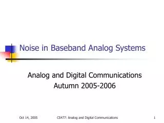
Types of Noise 1- Manmade (artificial):These could be eliminated via better design - Machinery - Switches - Certain types of lamps 2- Natural - Atmospheric noise: causing crackles on our radios - Cosmic noise (space noise): Noise in Electrical Components • Thermal noise: Random free electron movement in a conductor (resistor) due to • thermal agitation • Shot noise: Due to random variation in current superimposed upon the DC value. • It is due to variation in arrival time of charge carriers in active devices. • Flicker noise: Observed at very low frequencies, and is thought to be due to • fluctuation in the conductivity of semiconductor devices. Z. Ghassemlooy
p(vn) 0.4/ vn -3 - 0 2 3 -2 Gaussian Noise Each noise types outlined before (except flicker noise) is the result of a large number of statistically independent and random contributions. The distribution of such random noise follow a Gaussian distribution with zero mean. Where 2 is the variance of noise voltage vn For zero mean, normalised noise power or mean square voltage: Probability density function of zero mean and standard deviation Z. Ghassemlooy
vn t t+ t White Noise The time-average autocorrelation function of the noise voltage is: Assumptions: • vn(t+) is random value that does not depend on vn(t). • The above condition holds no matter how small is, provided it is not zero. White noisew(t) (i.e perfect randomness, which can not be attained in real systems) Z. Ghassemlooy
Sw(f) f Sw(f) o f White Noise - cont. The autocorrelation of white noise is: Rw(t) is a zero width of height Pn with an area under the pulse = o/2 o/2 Double-sided power spectral density Single-sided power spectral density Z. Ghassemlooy
White noise w(t)Sw(f) Narrow band noise vn(t) Sv(f) Sv(f) Sw(f) o f o B Sv(f) f o f fc-B/2 fc+B/2 fc-B/2 fc+B/2 fc fc Narrowband Noise Communication Receiver H(f) B Ideal LPF Ideal BPF Z. Ghassemlooy
White noise w(t)Sw(f) Narrow band noise vn(t) Sv(f) o o Sw(f) fc-B/2 fc+B/2 fc Sv(f) f f fc-B/2 fc+B/2 fc Narrowband Noise - cont. Bandpass Filter H(f) 1 Bandlimited noise x(t) and y(t) have the same power as the band pass noise vn(t) Z. Ghassemlooy
y(t) Quadrature component R(t) (t) x(t) Inphase component Narrowband Noise - Phasor diagram Bandlimited noise and x(t) and y(t) have the same power as the band pass noise vn(t) Z. Ghassemlooy
Sv(f) Ideal filter o w(t) vn(t) Beq Noise Equivalent Bandwidth • The power Pn of the band limited noise vn(t) is given bt the area under its power spectral density as: Realisable filter H(f) Noise equivalent bandwidth We replace realisable filter H(f) with a unit-gain ideal filter of bandwidth Beq. Z. Ghassemlooy
R = 300 Vin(t) Vout(t) C = 132.63 nF Noise - Example: a simple RC low-pass filter A simple RC low-pass filter is shown in figure below: • Find the noise equivalent bandwidth Beq? • Find the 3-dB bandwidth B of the filter? • Calculate the noise power Pn at its output when connected to a matched antenna • of noise temperature Ta = 80 K? (Assuming the filter is noise free) • How much error is incurred in noise power calculation by using the 3-dB • bandwidth in place of the Beq? Z. Ghassemlooy
Solution • The transfer function of the filter is: Amplitude response where Phase response Equivalent bandwidth Note: = 2f and a = 2RC The form of integral suggest the to use substitution of af = tan Z. Ghassemlooy
So & No Incoming signal Output signal SNRo SNRi White noise w(f) System Signal-to-Noise Ratio (SNR) Si Ni BPF (fc) Demodulator (Gd) + The SNR at the demodulator output is: Where - SNRi is the input signal (modulated carrier) to noise ratio - Gd is the demodulator gain. - Si = Total power in the received modulated signal - So = Power in the recovered message signal m(t) - Band limited noise power Ni = Pn = 2 Z. Ghassemlooy