Disciplines in EE Controls and Robotics
800 likes | 1.02k Vues
Disciplines in EE Controls and Robotics. Dan Popa, Ph.D., Associate Professor popa@uta.edu , http://ngs.uta.edu Systems Approach and Related Concepts - Review Feedback Control Basics Feedback Control History Robotics Basics Robotics History Examples. Signals and Systems. Signal:

Disciplines in EE Controls and Robotics
E N D
Presentation Transcript
Disciplines in EEControls and Robotics Dan Popa, Ph.D., Associate Professor popa@uta.edu, http://ngs.uta.edu • Systems Approach and Related Concepts - Review • Feedback Control Basics • Feedback Control History • Robotics Basics • Robotics History • Examples
Signals and Systems • Signal: • Any time dependent physical quantity • Electrical, Optical, Mechanical • System: • Object in which input signals interact to produce output signals. • Some have fundamental properties that make it predictable: • Sinusoid in, sinusoid out of same frequency (when transients settle) • Double the amplitude in, double the amplitude out (when initial state conditions are zero)
System Modeling • Building mathematical models based on observed data, or other insight for the system. • Parametric models (analytical): ODE, PDE • Non-parametric models: graphical models - plots, look-up cause-effect tables • Mental models – Driving a car and using the cause-effect knowledge • Simulation models – Many interconnect subroutines, objects in video game
Types of Models • White Box • derived from first principles laws: physical, chemical, biological, economical, etc. • Examples: RLC circuits, MSD mechanical models (electromechanical system models). • Black Box • model is entirely derived from measured data • Example: regression (data fit) • Gray Box – combination of the two
White Box Systems: Electrical • Defined by Electro-Magnetic Laws of Physics: Ohm’s Law, Kirchoff’s Laws, Maxwell’s Equations • Example: Resistor, Capacitor, Inductor
Linear Time-Invariant Models • Continuous-time linear dynamical system (LDSC) has the form dx/dt= A(t)x(t) + B(t)u(t), y(t) = C(t)x(t) + D(t)u(t) • where: • t R denotes time • x(t) Rn is the state (vector) • u(t) Rm is the input or control • y(t) Rp is the output
Linear Systems in Practice • most linear systems encountered are time-invariant: A, B, C, D are constant, i.e., don’tdepend on t • Examples: second-orderelectromechanicalsystemswith constant coefficients • when there is no input u (hence, no B or D) system is called autonomous • Examples: filters, uncontrolled systems • when u(t) and y(t) are scalar, system is called single-input, single-output (SISO) • when input & output signal dimensions are more than one, MIMO • Example: Aircraft – MIMO
Linear System Description in Frequency Domain • Purpose of Frequency Domain Analysis: • Convert Differential equations into Algebraic Equations • Interconnect systems using block diagrams • Use graphical tools to discover of influence behavior of systems
EE-Specific Diagrams • Block Diagram Model: • Helps understand flow of information (signals) through a complex system • Helps visualize I/O dependencies • Equivalent to a set of linear algebraic equations. • Based on a set of primitives: Transfer Function Summer/Difference Pick-off point U U2 + U1 U1+U2 U U +
Automatic Control • Control: process of making a system variable converge to a reference value • If r=ref_value=changing - servo (tracking control) • If r=ref_value=constant - regulation (stabilization) • Open loop vs. closed loop (feedback) control + y + y + r Controller K(s) Plant G(s) Controller K(s) Plant G(s) r - Sensor Gain H(s)
Brief History of Feedback Control • The key developments in the history of mankind that affected the progress of feedback control were: • 1. The preoccupation of the Greeks and Arabs with keeping accurate track of time. This represents a period from about 300 BC to about 1200 AD. (Primitive period of AC) • 2. The Industrial Revolution in Europe, and its roots that can be traced back into the 1600's. (Primitive period of AC) • 3. The beginning of mass communication and the First and Second World Wars. (1910 to 1945). (Classical Period of AC) • 4. The beginning of the space/computer age in 1957. (Modern Period of AC).
Primitive Period of AC Float Valve for tank level regulators Drebbel incubator furnace control (1620) (antiquity)
Primitive Period of AC James Watt Fly-Ball Governor For regulating steam engine speed (late 1700’s)
Classical Period of AC • Stability Analysis: Maxwell, Routh, Hurwitz, Lyapunov (before 1900). • Electronic Feedback Amplifiers with Gain for long distance communications (Black, 1927) • Stability analysis in frequency domain using Nyquist criterion (1932), Bode Plots (1945). • PID controller (Callender, 1936) – servomechanism control • Root Locus (Evans, 1948) – aircraft control • Most of the advances were done in Frequency Domain.
Modern Period of AC • Time domain analysis (state-space) • Bellmann, Kalman: linear systems (1960) • Pontryagin: Nonlinear systems (1960) – IFAC • Optimal controls • H-infinity control (Doyle, Francis, 1980’s) – loop shaping (in frequency domain). • MATLAB (1980’s to present) has implemented math behind most control methods.
Feedback Control • Role of feedback: • Reduce sensitivity to system parameters (robustness) • Disturbance rejection • Track desired inputs with reduced steady state errors, overshoot, rise time, settling time. • Systematic approach to analysis and design • Select controller based on desired characteristics • Predict system response to some input • Speed of response (e.g., adjust to workload changes) • Approaches to assessing stability
Feedback System Block Diagram • Temperature control system
Feedback System Block Diagrams • Automobile Cruise Control
Block Diagram of Feedback Disturbance Reference Value + S S Plant Controller – Transducer
Key Transfer Functions Reference + Plant Controller S – Transducer
Effect of pole locations Oscillations (higher-freq) Im(s) Faster Decay Faster Blowup Re(s) (e-at) (eat) Positive feedback Pole at 1/A (unstable) Negative feedback Pole at -1/A (stable)
Summary of Basic Control • Proportional control • Multiply e(t) by a constant • PI control • Multiply e(t) and its integral by separate constants • Avoids bias for step • PD control • Multiply e(t) and its derivative by separate constants • Adjust more rapidly to changes • PID control • Multiply e(t), its derivative and its integral by separate constants • Reduce bias and react quickly
Conclusion: Control Systems • Abstraction is the basis for system level thinking. Abstraction requires advanced mathematics, and it is especially required of Electrical and Computer Engineers. • Control Theory contains abstractions and generalizations able to guarantee predictable performance of systems under control. • Negative feedback offers numerous advantages: noise rejection, robustness to plant variations, dynamical tracking performance. • Examples of popular control schemes include Proportional-Integral-Derivative (PID) schemes. • Modern control is primarily based on time-domain analysis of state-equations using matrices. • Control engineers can find jobs in any industry. Control concepts can be applied in any engineering industry.
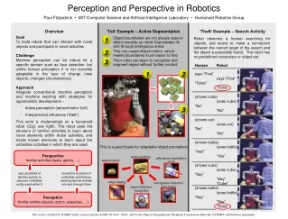
Robots as Complex Systems Controlled by Feedback G. Bekey definition: an entity that can sense, think and act. Classification: manipulators, mobile robots, mobile manipulators. Sense Think Act Robot
Robot Subsystems • A mechanical structure. • For manipulators this structure consists of a set of rigid bodies (links), connected by means of articulations (joints). Links and joints can also be described in terms of an arm (for mobility), a wrist (for dexterity) and an end-effector (for performing the task). • For mobile robots, the structure consists of a chassis with a locomotion mechanism, in the form of legs, wheels, rotor blades, etc. • Actuators. These set the robot in motion through actuation of its joints, and are typical electric or hydraulic. • Sensors. These measure the status of the manipulator (propriceptive sensors) and the status of the environment (heteroceptive sensors). • A control system. This enables control and supervision of the robot, and is usually a computer with a graphical user interface, a pendant, or a remote controller.
Mechanics of Manipulators • We describe robotic manipulators in terms of their degrees of freedom (DOFs). • 6 DOFs are needed to position and orient an object in a unique way in the 3D space. • Most robots have no more than 6 degrees of freedom. If they do, they are called redundant robots. Redundant robots can be ideal for situations requiring reaching out behind certain obstacles. • The manipulator links are connected together in chains. Chains can be open or closed. • Manipulators with open chains are also called serial, while the ones with closed chains are called parallel. • Joints allow relative motion between links, and can be rotary (revolute – R ) or linear (prismatic –P ). • The workspace of the manipulator is the total volume swept out by the end-effector of the manipulator. • The workspace may be constrained by the fact that not all joints can rotate 360 degrees. • The workspace is defined in terms of point reachable with arbitrary orientations (dextrous workspace) or fixed orientations (reachable workspace).
Typical Industrial Robot • 6 DOFs • Controller
Examples of industrial manipulator geometries Revolute “RRR”
Examples of industrial manipulator geometries Cartesian “PPP”
Examples of industrial manipulator geometries • “SCARA” • 3R+P
Examples of industrial manipulator geometries • Parallel • Stewart platform
Mobile Robots • Wheeled (incl. tracks) • Legged • Aerial • Underwater
Basic Concepts • In robotics we are constantly concerned with the location of objects in 3D space. • In order to describe it we attach a coordinate frame rigidly to an object, or to the manipulator. We then transform the position and orientation from one frame to another. The frame associated with the non-moving parts of the manipulator is called the base frame, and the one attached to the end-effector is called the tool frame.
Basic Concepts • Kinematics is the science of motion based on geometric description, regardless of the forces which cause it. Kinematics deals with positions and its derivatives (velocity/acceleration). • The number of DOFs of the manipulator equals the number of independent position variables that would have to be specified in order to locate all parts of the mechanism. It equals the number of joints in an open kinematic chain. • Forward Kinematics refers to the problem of computing the position and orientation of the end-effector relative to the base frame given a set of joint angles. • Cartesian space (or task space, operational space) is the usual 3D Euclidian space for position and orientation (6 DOFs). The joint space (or configuration space) is the space in which the manipulator is described by it’s joint angles. • Inverse kinematics is the problem of inverse mapping between end-effector positions and orientation and the joint angles. We need to map locations in task space to the robot’s internal joint space.
Basic Concepts • Dynamics is devoted to studying the forces required to cause motion. • The relationship between the joint actuator torques, the accelerations of the robot, and the other external forces (gravity of links and payload, external forces exerted) is studied within the context of dynamics. • Dynamics is important if we use high velocities to actuate the system. • If there is no motion involved, the force/torque balancing analysis is also called manipulator statics • Kinematics is usually sufficient if the robot is gravity compensated and moves at slow speeds. • Dynamics is necessary for simulation and control. • Motion planning refers to the study of generating motion for the robot to accomplish a task. This consists of : • Path planning - generating a feasible path from an initial position to a final position by describing the geometric position and orientation of the robot during the transition. Sometimes this path must avoid obstacles in the task space, and it may be described by intermediate points (also called via-points). Sometimes the path is a spline (e.g. a smooth function that passes through a set of via points). • Trajectory generation – attaching a time frame to the paths generates a trajectory. The trajectory not only describes the position of the robot during motion, but also how that position changes with time.
Basic Concepts • Manipulator control refers to a closed-loop feedback system that uses sensory information to control the motion of the manipulator. A controller accomplishes : • Trajectory tracking – following the prescribed trajectory for the manipulation. • End-point control - reaching a goal configuration in either task or joint space irrespective of the trajectory it is achieved. This is also called the stabilization problem. • Position/velocity control – compensates for errors in knowledge of the systems parameters and suppresses disturbances. Control algorithms can be linear or nonlinear. • Force control – Controlling the force exerted by the manipulator onto an object in a single or multiple degrees of freedom. Can be reduced to position control if the stiffness of the manipulator and object are known, but it usually requires force sensing. Sometimes a scheme called hybrid control is used, e.g. controlling force along certain DOFs and position along other DOFs. • Robot Programming – Modern robots use robot programming languages to describe tasks from users. Programming could be on-line (with the robot attached) and off-line (with a dynamic simulation model of the robot). The issue of safety should be carefully considered when implementing on-line robot motion. Often time robotic cells have interlocked protective enclosures and fences.
History of Robotics • Robotics was first introduced into our vocabulary by Czech playwright Karel Capek in his 1920’s play Rossum’s Universal Robots. • The word “robota” in Czech means simply work. Robots as machines that resemble people, work tirelessly, and revolt against their creators. • The same myth/concept is found in many books/movies today: • “Terminator”, “Star-Wars” series. • Mary Shelley’s 1818 Frankenstein. • Frankenstein & The Borg are examples of “cybernetic organisms”. • Cybernetics is a discipline that was created in the late 1940’s by Norbert Wiener, combining feedback control theory, information sciences and biology to try to explain the common principles of control and communications in both animals and machines. • “Behavioral robotics”: organisms as machines interacting with their environment according to behavioral models.
Manipulators • Industrial manipulators were born after WWII out of earlier technologies: • Teleoperators. Teleoperators, or remotely controlled mechanical manipulator, were developed at first by Argonne and Oak Ridge National Labs to handle radioactive materials. These devices are also called “master-slave”, and consisted of a “master” arm being guided through mechanical links to mimic the motion of a “slave” arm that is operated by the user. Eventually, the mechanical links were replaced by electrical or hydraulic links. • Numerically controlled milling machines (CNC). CNC machines were needed because of machining needs for very complex and accurate shapes, in particular aircraft parts.
Mobile Robots • Mobile robots were born out of “unmanned vehicles”, which also appear in WWII (for example an unmanned plane dropped the atomic bomb at Nagasaki). • Unmanned Aerial Vehicles (UAV), Underwater Vehicles (UUV) and Ground Vehicles (UGV). • Because tethered mobile vehicles could not move very far, and radio communications were limited, an approach to mobile robots is to endow them with the necessary control and decision capability - “autonomy” • Autonomous Underwater/Ground/Aerial Vehicles (AUV/AGV/AAV). • Unlike manipulators, we do not think of a remotely controlled toy as a mobile robot, suggesting that one of the fundamental aspects of mobile robotics is the capacity for autonomous operation.
Robot History Timeline • 1947-1949 – first electric and hydraulic teleoperators are developed by General Electric and General Mills. Force feedback is added to prevent the crushing of glass containers during manipulation. • 1949 - CNC machine tools for accurate milling of aircraft parts are introduced. • 1953 – W. Grey Walter applies cybernetics principles to a robotic design called “machine speculatrix”, which became a robotic tortoise. The simple principles involved were: • Parsimony: simple is better. Simple reflexes are the basis of robot behavior. • Exploration or speculation: the system never remains still except when recharging. Constant motion is needed to keep it from being trapped. • Attraction: the system is motivated to move towards objects or light. • Aversion: the system moves away from certain objects, such as obstacles. • Discernment: the system can distinguish between productive and unproductive behavior, adapting itself to the situation.
G. Walter Grey's tortoise These vehicles had a light sensor, touch sensor, propulsion motor, steering motor, and a two vacuum tube analog computer.
Robot History Timeline • 1954 – George Devol replaced the slave manipulator in a teleoperator with the programmability of the CNC controller, thus creating the first “industrial robot”, called the “Programmable Article Transfer Device”. • 1955 – The Darmouth Summer Research Conference marks the birth of AI. Marvin Minsky, from the AI lab at MIT defines an intelligent machine as one that would tend to “build up within itself an abstract model of the environment in which it is placed. If it were given a problem, it could first explore solutions within the internal abstract model of the environment and then attempt external experiments”. This approach dominated robotics research for the next 30 years. • 1956 - Joseph Engleberger, a Columbia physics student buys the rights to Devol’s robot and founds the Unimation Company. • 1961 – The first Unimate robot is installed in a Trenton, NJ General Motors plant to tend a die casting machine. The key was the reprogrammability and retooling of the machine to perform different tasks. The Unimate robot was an innovative mechanical design based on a multi-degree of freedom cantilever beam. The beam flexibility presented challenges for control. Hydraulic actuation was eventually used to alleviate precision problems.